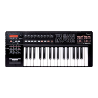
AX-7
Nov, 2001
1
SERVICE NOTES
Issued by RES
First edition
Copyright © 2001 by ROLAND CORPORATION
All rights reserved. No parts of this publication may be reproduced in any form whithout the written permission of ROLAND CORPORATION.
SN00058 K6018458 Printed in Italy (I00) (AD)
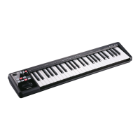
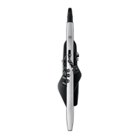
aX-7
midi keyboard controller
TABLE OF CONTENTS Page
SPECIFICATIONS 1
LOCATION OF CONTROLS 2
EXPLODED VIEW (TOP) 3
EXPLODED VIEW (BOTTOM) 3
KEYBOARD PARTS LIST 4
PARTS LIST 4/5
HOW TO VISUALIZE THE SYSTEM PROGRAM VERSION 6
HOW TO CARRY OUT THE FACTORY SETUP 6
HOW TO ENTER TEST MODE 6
BLOCK DIAGRAM 9
CPU PCB ASSY 10
CIRCUIT DIAGRAM (CPU PCB ASSY 1/3) 11
CIRCUIT DIAGRAM (CPU PCB ASSY 2/3) 12
CIRCUIT DIAGRAM (CPU PCB ASSY 3/3) 13
LEFT CONTROL PCB ASSY 14
RIGHT CONTROL PCB ASSY & CIRCUIT DIAGRAM 15
DISPLAY PCB ASSY & CIRCUIT DIAGRAM 16
D-BEAM PCB ASSY & CIRCUIT DIAGRAM 16
CONTACT PCB ASSY W/ RUBBER & CIRCUIT DIAGRAM 17
Specifications
Keyboard: 45-key keyboard with Velocity Sensitivity (TP-7 BA type)
Display: 3 x 7 segments display view control
Realtime controllers: Data Entry Knob, Touch Controller, Expression Bar, Hold Button, D-Beam
Memories: 128 Patches
Connections: MIDI In, Out; DC IN (adaptor)
Power supply : Battery-operated, Optional AC/DC Adaptor ACA (DC 9V)
Dimension: 1010 (W) x 195 (D) x 102 (H) mm
Weight:: 3,0 Kg
Supplied accessories: 6 x dry batteries (AA type), MIDI cable, Owner’s Manual, Shoulder strap
Specifications subject to change without prior notice. All other trademarks mentioned in this manual are the property of the respective companies.
DISASSEMBLY