Do you have a question about the Roland E-X20 and is the answer not in the manual?
User data cannot be backed up to external media or written on paper, posing a data loss risk.
Lists included accessories like owner's manuals, AC adaptors, and music rests for the unit.
Checks and displays the current firmware version number of the E-X20/E-X20A.
Evaluates the functionality and visual quality of the unit's LCD screen.
Verifies that all physical function buttons on the keyboard operate correctly.
Tests the responsiveness and accuracy of each individual key press.
Confirms that connected pedals are recognized and function as expected.
Inspects Analog-to-Digital Converter inputs, likely for control signals.
Outputs various audio signals to test speaker and audio path integrity.
Checks the USB data interface and internal RAM/ROM memory for proper operation.
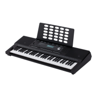
This document provides service notes for the Roland E-X20 and E-X20A Arranger Keyboards, covering various aspects from general information to detailed test procedures. It is intended for service personnel to facilitate maintenance and repair.
The manual begins with "Cautionary Notes" emphasizing the importance of reading the document thoroughly before starting any procedure, as details may vary by model. It also highlights that user data cannot be backed up to external media or written on paper, which is a crucial point for technicians to remember when performing service that might involve data loss.
A "Parts List" section explains that certain components with a part code of "********" will not be supplied as service parts due to various reasons. These reasons include being supplied as assembled parts, grouped circuit boards, copyright restrictions, reissuance restrictions, made-to-order parts, electronic data availability on the Roland website, or being irrelevant to the main body's function maintenance (e.g., accessories or packaging). This information is vital for understanding part availability and ordering.
The "Exploded View" provides a visual breakdown of the keyboard's internal components, accompanied by an "Exploded View Parts List" that details each numbered part, its code, name, description, and quantity. This section is essential for identifying and locating specific components during disassembly and reassembly. For instance, it lists the ROTATE WHEEL ASSY, JACK BOARD ASSY, VOLUME BOARD ASSY, MAIN BOARD ASSY (with separate part codes for E-X20 and E-X20A), ENCODER BOARD ASSY, FUNCTION BOARD ASSY, SPEAKER, RUBBER SWITCH 13P, KEYSCAN BOARD, various NATURAL KEY groups, SHARP KEY, and BATTERY COVER. A special note advises that when replacing the RUBBER SWITCH 13P for positions other than the highest (right end) of the keyboard, a 1P cut is needed to change it to 12P. Another note states that if parts other than those listed are required for repair, the entire product should be replaced.
The "Accessories Parts List" enumerates the items that come with the keyboard, such as the MUSIC REST, OWNER'S MANUAL (available in English and Chinese, with different part codes for E-X20 and E-X20A), the "USING THE UNIT SAFELY" leaflet, and various AC ADAPTORS tailored for different voltage regions (e.g., 117VBL, 117VU/CS, 230VEU, 230VIN, 230VE, 220VCN). It also mentions optional accessories sold separately, such as the DP series pedal switch.
The "Connecting Wirings" section provides detailed diagrams and tables illustrating how the various internal boards and components are interconnected. It shows connections between the IO Board, Main Board, Function Board, Pitchbend cable, Volume cable, Speakers, and Battery cable. This information is critical for troubleshooting connectivity issues and ensuring correct reassembly after repairs. For example, it specifies that the IO Board BUSS2 connects to MB CN2, the Pitchbend cable to CN6, and the Function board BUSS1 to CN5. Separate tables detail connections from the Main board to other boards, the Function board to other boards, and the IO board to other connections, providing a clear roadmap for tracing signals and power.
The manual includes a "Revise Information" table, which is crucial for keeping track of updates to the service notes. It lists revisions made on specific dates (e.g., Mar. 29, 2019; Feb. 9, 2021; Mar. 4, 2022) and describes the changes, such as "Added a model," "Added a section," or "Added a part." This ensures that technicians are using the most current and accurate information.
The "System Self-test" section is a key diagnostic tool for technicians. It outlines a series of tests to check the functionality of various components.
Factory Reset: A "Factory Reset" can be performed by holding down [+/YES] and [-/NO] buttons while turning on the power. This is useful for restoring the device to its default settings.
Key Combination Instruction: Special functions can be accessed by holding specific key combinations during power-on:
Operating Instructions for Self-test: Before starting the self-test, the piano should be connected to a PC via a USB cable, and pedals should be connected. The [PLAY/STOP] button combined with [+] or [-] allows navigation between test items. The [VOLUME] knob should be turned to the Maximum level when entering System self-test mode.
Test 1: Display the Firmware Version Number: In Test 1, the LCD displays the firmware version (e.g., V1.0.0). Pressing and holding [START/STOP] then [+] proceeds to Test 2.
Test 2: LCD Inspection: This test checks the LCD's functionality. Pressing [+] starts the inspection, displaying test images like full screen light, full screen dark, and patterns of ">", "<", "#", "8", and "x" in the LCD lattice area. Technicians should check for ghost shadows or bad pixels. Holding [START/STOP] then [+] proceeds to Test 3.
Test 3: Function Buttons Inspection: The LCD displays "SHIFT". Pressing [+] starts the inspection. The LCD indicates the next button to check. Buttons should be checked from left to right. A "Clave" tone indicates a passed check, while a "Cymbal" tone indicates a failed check. After all buttons are checked, the LCD displays "PASS". The dial should be rotated anticlockwise past 10 and then clockwise back to 0 to pass its check. If a button check fails, the test stops until the error is resolved. Holding [START/STOP] then [+] proceeds to Test 4.
Test 4: Keys Inspection: The LCD displays "K61-C7" (key number and name). Pressing [+] starts the inspection. The LCD indicates the next key to check (e.g., K60-B6). Keys should be checked from right to left with medium velocity (40-90). A "Clave" tone indicates a correct key number and velocity, and MIDI data (NOTE ON event) is sent to the PC. A "Metronome2" tone indicates a correct key number but wrong velocity. A "Cymbal" tone indicates a wrong key number. If a key check fails, the test stops until the error is resolved. The test must be completed once started. Checking MIDI data on a PC can verify USB jack functionality and velocity level accuracy. Holding [START/STOP] then [+] proceeds to Test 5.
Test 5: Pedals Inspection: The LCD displays "Ped Test". After the pedals are checked, the LCD displays "PASS". Holding [START/STOP] then [+] proceeds to Test 6.
Test 6: ADC Inspection: The LCD displays "Adc Test L". Pressing [+] and rotating the master volume knob (left and right to MIN and MAX) starts the ADC inspection. The LCD displays the real-time ADC value (e.g., 127). When the knob is rotated to MIN and MAX, the LCD displays "ADC-PIT". If the pitch-bend is moved to MIN and MAX, the LCD displays "PASS". If an ADC check fails, the test stops until the error is resolved. The ADC inspection must be completed once started. Holding [START/STOP] then [+] proceeds to Test 7.
Test 7: Audio Test Signal Inspection: This test allows outputting specific audio test signals by pressing keys [C4]-[C#5]. The LCD indicates the current audio test signal. The manual provides a table listing various audio test signals (e.g., Left phase 1 kHz sine wave, Right phase 1 kHz sine wave, Max undistorted signal, 1 kHz sine wave, Church Organ, Sweep signal 1 & 2, White noise, 100 Hz sine wave, 300 Hz sine wave, 440 Hz sine wave, 10 kHz sine wave, AP test signal (IMD), AP test signal (MultiTone)) and their corresponding LCD displays. Pressing other keys (e.g., [C3]) stops the audio test signal, and the LCD displays "AU:OFF", allowing for static noise level checks. Rotating the volume knob during maximum undistorted signal output checks its functionality. Holding [START/STOP] then [+] proceeds to Test 8.
Test 8: Data Interface and Memory Inspection: The LCD temporarily displays "BACK:RUN" as a background inspection runs. Then, the LCD shows the test results. If an item fails, the LCD displays the failed item (e.g., "ROM") and a "Cymbal" tone. If all items pass, the LCD displays "PASS" and a "Clave" tone. The inspection items include A2S-RAM and A2S-ROM. This test runs automatically at power-on; to recheck, the digital piano must be restarted and the system self-test re-entered.
The "Appendix: Audio Test Signal" provides visual representations (oscilloscope screenshots) of the various audio test signals described in Test 7, such as Left phase, Right phase, Maximum undistorted signal, White noise, and sine waves at different frequencies (100 Hz, 300 Hz, 440 Hz, 10 kHz), as well as AP test signals (IMD and MultiTone). These visuals are invaluable for technicians to verify the correct output of audio signals during diagnostic procedures.
| Polyphony | 128 voices |
|---|---|
| Effects | Reverb, Chorus |
| Display | Custom LCD |
| Speakers | 12 cm x 2 |
| Metronome | Yes |
| Transpose | Yes |
| Octave Shift | Yes |
| Bluetooth | No |
| Keyboard | 61 keys |
| Amplifiers | 2.5 W + 2.5 W |
| Weight | 3.9 kg |
| Power Supply | AC adaptor or batteries |
| Connectors | USB |