Table of contents Page
SPECIFICATIONS 1
DISASSEMBLY 1
LOCATION OF CONTROLS 2
EXPLODED VIEW (TOP 1/2) 3
EXPLODED VIEW (TOP 2/2) 3
PARTS LIST OF EXPLODED VIEW (BOTTOM) 4
EXPLODED VIEW (BOTTOM) 5
WIRING DIAGRAM 6
KEYBOARD PARTS LIST 7
PARTS LIST 8/9/10
ATTENTION WHEN YOU HAVE TO CONNECT THE SWITCHING POWER SUPPLY SWM-65 10
BLOCK DIAGRAM 11
CPU PCB ASSY 12
CIRCUIT DIAGRAM CPU PCB ASSY 13
CIRCUIT DIAGRAM CPU PCB ASSY (LCD BLOCK) 14
CIRCUIT DIAGRAM CPU PCB ASSY (2ND UART CONTR. BLOCK) 14
CIRCUIT DIAGRAM CPU PCB ASSY (D BEAM BLOCK) 14
CIRCUIT DIAGRAM CPU PCB ASSY (KEYSCAN BLOCK) 14
CIRCUIT DIAGRAM CPU PCB ASSY (MEMORY BLOCK) 15
CIRCUIT DIAGRAM CPU PCB ASSY (FDC & SCSI BLOCK) 15
XPGS PRO PCB ASSY 16
CIRCUIT DIAGRAM XPGS PRO PCB ASSY 17
AUDIO PCB ASSY & CIRCUIT DIAGRAM 18
D BEAM PCB ASSY & CIRCUIT DIAGRAM 19
EQULIZ. PCB ASSY & CIRCUIT DIAGRAM 19
RIGHT CONTROL PCB ASSY 20
CIRCUIT DIAGRAM RIGHT CONTROL PCB ASSY 21
LEFT CONTROL PCB ASSY 22
CIRCUIT DIAGRAM 1/2 LEFT CONTROL PCB ASSY 22
CIRCUIT DIAGRAM 2/2 LEFT CONTROL PCB ASSY 23
CENTRAL PCB ASSY & CIRCUIT DIAGRAM 24
DEBOUNCE PCB ASSY & CIRCUIT DIAGRAM 25
PHONES PCB ASSY & CIRCUIT DIAGRAM 26
INVERTER PCB ASSY & CIRCUIT DIAGRAM 26
AFT PCB ASSY & CIRCUIT DIAGRAM 26
FC7 PCB ASSY & CIRCUIT DIAGRAM 26
MIDI PCB ASSY & CIRCUIT DIAGRAM 27
POWER AMP. PCB ASSY & CIRCUIT DIAGRAM 28
LEFT CONTACT PCB ASSY w/RUBBER CONTACT & CIRCUIT DIAGRAM 29
RIGHT CONTACT PCB ASSY w/RUBBER CONTACT & CIRCUIT DIAGRAM 29
HOW TO SAVE / HOW TO VERSION UP 30
TEST MODE 31/34
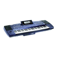
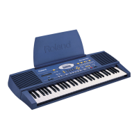
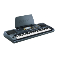
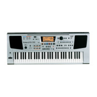
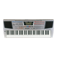
EM-2000
Oct, 1998
Specifications
Keyboard : 61 Keys, velocity sensitive with Channel Aftertouch.
Sound Source : SC-88 Pro Like, 32 Multitimbral Parts.
Maximum polyphony : 64 Voices
Tones : Enhanced variation tones (1161 Top-notch sounds + 43 drum Kits including Oriental kit)
GM-GS compatible
Wave Memory : 24MBytes.
Macro Editing : Vib Rate, Vib Depth, Vib Delay, Cutoff Freq, Resonance, Attack Time, Decay Time, Release Time.
Music Styles : 128 at high definition, Included 16 “Acoustic Styles” on Rom (120 Cpt/quarter note, with Pitch
Bender,: Control Change, etc..), 8 polyphonic tracks for each division.
Custom Styles : 16 on programmable Flash Eprom (8 tracks for each style). (Memory Backup at Power -Off)
Content of ZIP Disk : 441 Music Styles + 306 SMF Songs
Performance Memories : 192
Midi Sets : 8
16 Trk song sequencer : Complete MIDI editing (Quantize, copy, erase, delete, etc...)
Built-in Effects : Digital Reverb, Chorus, Delay, Parametric Equalizer, Insert Effects.
Hard Disk : Internal ZIP Driver.
SCSI : SCSI Socket for any external SCSI Devices.
Floppy Disk Drive : HD/DD-type for SMF playback without loading. Load/Save of User Styles, Performance Memories,
Midi Set, Chord Sequences.
Display : New Wide Graphic 240x64 pixel CCFL backlit LCD with software windows management.
Power Supply : Direct AC (Universal Switching Power Supply).
Jack/connectors : Stereo Phones, Output L/mono-R, Input L/Mono-R,Sustain Footswitch, Expression Pedal,
Programmable Foot Switch, External Multi switch pedal (FC7), MIDI (In, Out, Thru),
Controls : Master Volume (Slider), Balance (Slider),LCD Contrast (Rotative), Tempo (Encoder), Part Volume
(Encoder 5pcs), Bender & Modulation (Lever).
Output (L/Mono) Level : - 6 dBm Master Volume at maximum
Balance at center
Reverb at zero
Chorus at zero
Select Sine Wave Tone (D31 Var.7)
Play C4 key (Velocity at maximum)
Output Impedance : 680 Ohm
Input (L/Mono) Level : 0 dBm Power Amplifier at clipping
1KHz Sine Wave on External Input L/Mono
Input Impedance : 22K Ohm
Phones Output Level : + 8 dBm Master Volume at maximum
Balance at center
Reverb at zero
Chorus at zero
Select Sine Wave Tone (D31Var.7)
Play C4 key (Velocity at maximum)
30 Ohm Stereo Phones
Phones Output Impedence : 100 Ohm
Minimum Phones Impedence : 8 Ohm
Speakers : Two way Stereo System, in Bass Reflex boxes (2x10 cm Woofer, 2x3 cm Tweeter)
Amplification : 20W + 20W Musical Power.
Power Consumption : 70 W (AC 100V; AC 117V; AC 230V; AC240V)
Dimensions : 1176 (W) X 412 (D) X 165 (H) mm
Weight : 17 Kg
Option : PK-5; FC-7; MSA/MSD/MSE; RH-20/80/120; DP-2; DP-6; FS-5U; EV-5; BOSS FV-300L; KC-
100/300/500
Accessories : See “ EM-2000 Parts List “ on page 10.
1
SERVICE NOTES
Issued by RES
Copyright © 1998 by ROLAND CORPORATION
All rights reserved. No parts of this publication may be reproduced in any form whithout the written permission of ROLAND CORPORATION.
DISASSEMBLY
First Edition
SN00025 K6018341 Printed in Italy (AD00) (AD)
EM-2000
CREATIVE KEYBOARD
64 VOICE POLYPHONY