40
Mar.2004
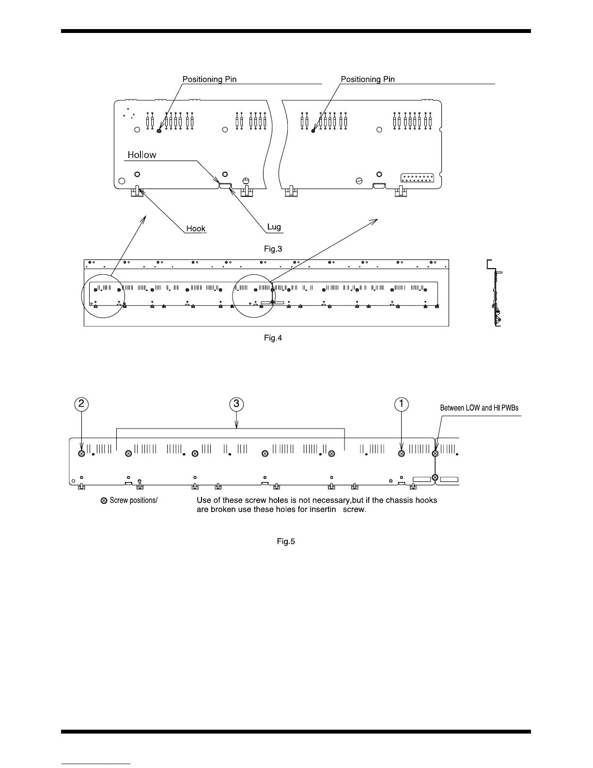
2. Aligning the cutouts in the PWB with the lugs on the chassis, put one side of the PCB into the chassis hooks. Place the PCB on the Chassis so that the chassis
positioning pins fit into the positioning holes. (See fig.3) At this point, the chassis positioning reference pin should first be fitted into the hole. There are two PCBs,
LOW and HI, as shown in fig.4. The Chassis positioning reference pins are located near the connector each of the LOW and HI PCBs.
fig.3-4-e
3. Then, using the screws, fasten the LOW and HI PCBs to the chassis from the center of the keyboard, that is,from the LOW PCB as shown in fig.5. While you are
screwing down the PCB, it may float from the chassis. To avoid this, after screwing in the PCB at the center of the keyboard, screw down opposite end, before
screwing in other areas in the middle of the PCB. (See fig.5) In addition, the PCBs may be warped by soldering, etc. It is recommended that each PCB be fastended
screws while holding down the middle of the PCB lightly. Finally, screw down the adjacent area between the LOW and HI PCBs.
fig.5-e
Note) When using an electric screwdriver, be careful of the torque. If excessive force is applied, the PCB may break or chip. (Suitable torque:8kgf-cm)
* ** * * * *
*

 Loading...