GT-3 Feb. 1999
12
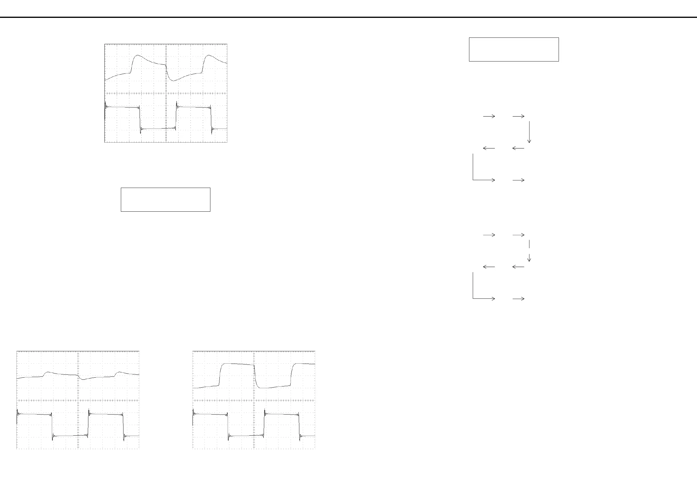
OUTPUT level control:MAX
Oscilloscope:0.5V/DIV,0.5mS/DIV
fig. 4
Press the button [EXIT] to proceed to the next test.
11.DS A/D/A[CV CHECK ]
10.DS A/D/A:CV
00[CV CHECK ]0 0
The CV level sweeps from 0 to 100. Verify smooth waveform
level change.
NOTE: This test cannot be interrupted until one CV sweep
cycle completes. (0-100-0)
NOTE: For the following measurements, first connect the
oscilloscope to OUTPUT R. Repeat the measurement by
connecting the scope to OUTPUT L(MONO) with the blank
plug inserted in OUTPUT R.
OUTPUT level control:MAX
Oscilloscope:0.5V/DIV,0.5mS/DIV
CV CHECK=0 CV CHECK=100
←→
fig. 5
Press the button [EXIT] to proceed to the next test.
12. EXT OD CHECK
12.EXT0 OD0 CHECK
00[DSP→ EXT→ OUT]
Check the signal path:
A) Connect the oscilloscope to either OUTPUT socket and
verify rectangular output waveform.
ESP D/A SEND
(Signal source)
ESP A/D RETURN
D/A OUTPUT
(Rectangular waveform)
B) Insert the blank plug into RETURN socket and verify
discontinued signal path.
ESP D/A SEND
(Signal source)
---x-- (Cut off)
ESP A/D RETURN
D/A OUTPUT
(Rectangular)
NOTE: For the following measurements, first connect the
oscilloscope to OUTPUT R. Repeat the measurement by
connecting the scope to OUTPUT L(MONO) with the blank
plug inserted in OUTPUT R.
OUTPUT level control:MAX
Oscilloscope:0.5V/DIV, 0.5mS/DIV
12.EXT OD CHECK
下記の2点を確認してください。
A) OUTPUTから矩形波が出力される事をオシ
ロスコープで観測してください。
B) RETURNジャックにオープン・プラグを
差し込んで、出力が無くなることを確認して
ください。
注意:チェックはL(MONO)、Rの両方行ってくださ
い。また、OUTPUTジャックをL(MONO)チャンネル
単体で使用した場合、L,Rの信号は内部でミキシング
されるため、L(MONO)チャンネルの測定時には必ず
Rチャンネルに空プラグを挿入してください。
[EXIT]ボタンを押すと、次の検査に進みます。
11.DS A/D/A[CV CHECK ]
OUTPUTからの波形をオシロスコープで観測して
CVが0〜100の間で変化していることを確認しま
す(右下にCV値が表示されます)。
CV変化が最大値と最小値の間を1往復するまでは次
の検査項目へは進めません。
注意:チェックはL(MONO)、Rの両方行ってくださ
い。また、OUTPUTジャックをL(MONO)チャンネル
単体で使用した場合、L,Rの信号は内部でミキシング
されるため、L(MONO)チャンネルの測定時には必ず
Rチャンネルに空プラグを挿入してください。
[EXIT]ボタンを押すと、次の検査に進みます。
/発振)
/矩形波)
/発振)
/切断)
/矩形波)
 Loading...