MT
-
32 will never require
any data of the other party. The following
sequence can
apply
to the
outside
world
where a unit wants to get
MT
-
32 resident parameters.
Receiver
[RQDj
Outside unit
such as a
coaputer
can obtain WT-32 paraaeters
by
following
the steps
below,
starting
with transmission of Data request.
Transainer(MT-32)
(
<
[RJCj
)
(Ends current coaaunication
upon
Kill
send this aessage when )
(receipt of this aessage.
Data request cones while ft )
)
is reproducing sound.
-(DAT]
When the Data request coees
during
no-sound period
and
contains
address listed In the
Paraaeter bade sddress table
followed
by 1 or nore address
size,
MT-
32
will send
the data
stored in that address
area
and
subsequent.
If
the address Batches the
paraaeter bade address,
stores
the data
into that location; then
sends Acknowledge.
CACK)
Sends the next
data
in
reply
to Acknowledge.
<
[DAT]
EACK)
>
(
(ERR]
>
(should
failure In data reception When receiving
this
sessage,
(occurte.g. disagreement
of checksum), sends the previous
data
(sends this sessage.
again.
(
<
[
DAT
j
<
[EOD]
sends Acknowledge
In response to
Sends this data when coapleting
Data end and tersinates
handshaking
required data transfer.
communication.
[ACK]-
When
this
aessage coees
as an
answer
to the Data end,
terai nates
coaaunication.
*
4
-
1 Address and Address
size must cover the memory
location where data
exist.
*
5
-
i Start address plus
two
offset addresses
( in tables
*
5
-
1 and
*
5
-
1
-
1 (* 5
-
I
-
2)
)
*
5
-
2 Start address plus one offset address
(
in
tables
* 5
-
2
)
*
5
-
3 Start address plus
two
offset addresses
( in
tables
*S-3
and *5
-
3
-
1 )
*
5
~
4
-
*
5
-
7 Start address plus one
offset address
( in
tables
*
5
-
4
-
*5-7}
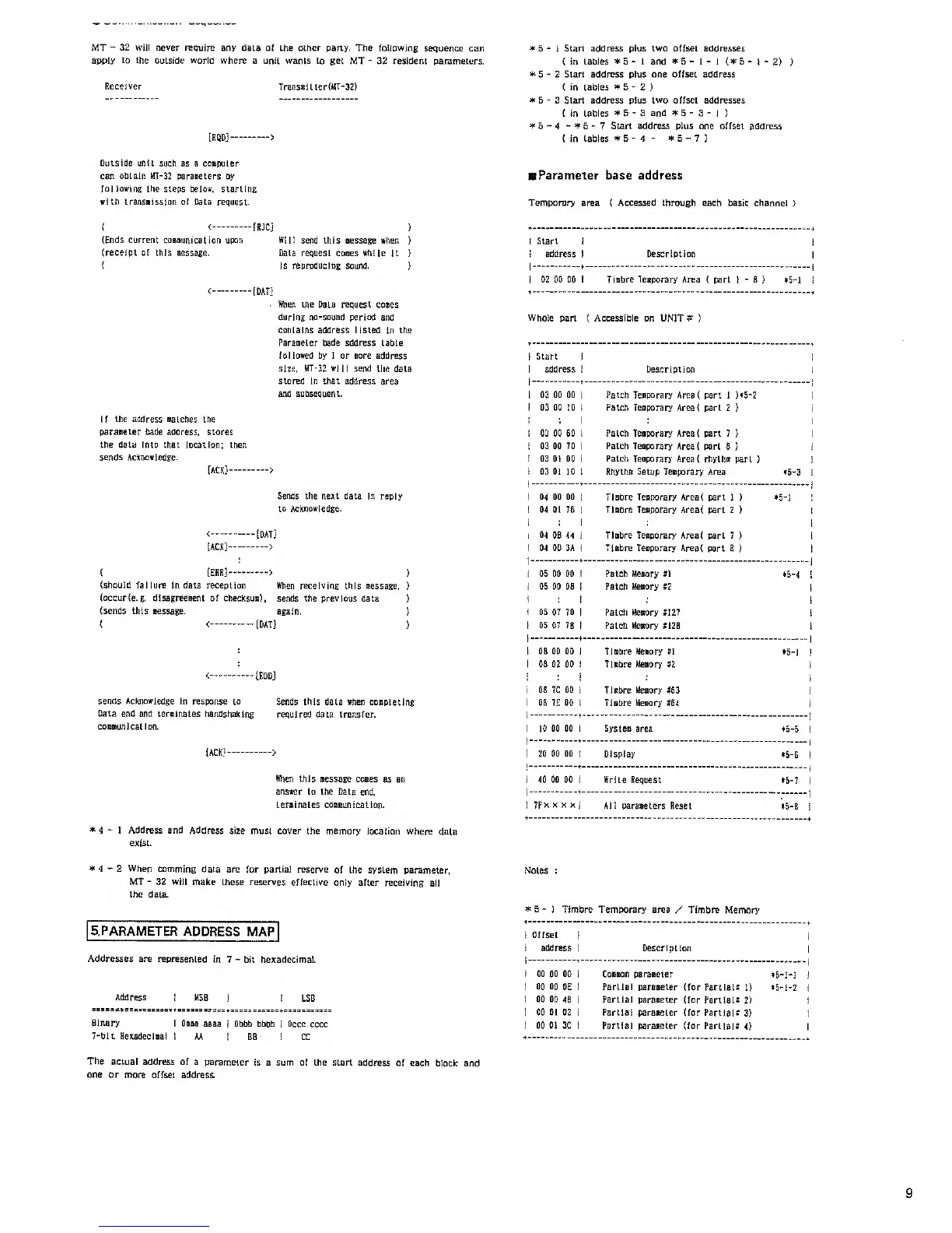
B
Parameter
base
address
Temporary area ( Accessed through each basic
channel )
Start
address Description
02 00 00 Tiabre Tesporary Area
(
part 1
-
8
) *5-l
Whole
part ( Accessible on UNIT*
)
1 Start
i
1 address
I
Description
1 03 00 00
I
! 03 00 to
1
!
03 00 60
1
! 03 00 70
1
i 03 0! 00
1
1
03 01 10
1
Patch
Teaporary Area( part 1
)»5-2
Patch Teaporary Area( part
2
)
Patch Teaporary Are3( part 7
)
Patch Teaporary Area( part
8
}
Patch Teaporary Area( rhytlw
part
)
Rhyths Setup
Teaporary Area
•5-3
i
1 04 00 00
j
j 04 01
76
|
i :
I
i
04
0B 44
I
1 04 GD 3A
j
Tiabre
Teaporary
Area( part
1 )
Tiabre Teaporary
Area( part 2
)
Tiabre Tesporary Area( part 7
)
Tiabre Teaporary Area(
part 8
)
5-1
!
1 05 00 00 !
j 05 00 08
!
1 :
!
i
05 07 70
|
1 05 07 78
1
Patch Meaory
»1
Patch Meaory *2
Patch
Meaory
?127
Patch
Meaory
*!2B
5-4
!
1 08 00 00 1
1 08 02 00 i
!
:
i
i
08 7C 00
|
1
08
7E
00
1
Tlobre Meaory
*1
Tiabre Meaory
*2
Tiabre Meaory *63
Tiabre Meaory
#64
5-1
1
j
10
00 00
!
Systea area 5-5
i
i 20 00 00
1 Display 5-6
1
i 40 00 00 I
Write
Request 5-7
1
|
7Fx
x x x
|
All parameters Reset 5-8
i
*
4
-
2
When
comming data
are for partial reserve of
the system parameter,
MT
-
32
will
make these
reserves
effective
only after receiving
all
the data.
5.PARAMETER
ADDRESS MAP
Addresses
are
represented
in 7
-
bit
hexadecimal.
Address
MSB
LSB
Binary
I
Oaaa
aaaa 1 Obbb bbbb ! Occc cccc
7-olt.
Hexadeclaa!
i
AA
I
BB I CC
The actual
address of a parameter
is a sum of the start
address of each block
and
one or more offset
address.
Notes :
* 5
-
1
Timbre
Temporary area / Timbre
Memory
Offset
|
address
1 Description
00 00 00
i
Cosaon
paraaeter
5-i-J 1
00 00
0E
1
Partial paraaeter (for
Partial*
1)
5-1-2
t
00 00
48
i
Partial paraaeter (for
Partial* 2)
00 01 02
1
Partial
paraaeter (for Partial*
3)
00 01 3C
1
Partial
paraaeter (for Partial*
4)
 Loading...