EasyManua.ls Logo

Roland RE-501 Service Manual

Roland RE-501
12 pages
To Next Page IconTo Next Page
Page #1 background imageLoading...
Page #1 background image
JULY
11,1980
RE-501
/SRE-555
RE-501
SRE-555
SERVICE ilOTCS
SPECIFICATIONS
Input Level/Impedance
Balanced:
Unbalanced:
Output
Level/Impedance
Balanced:
Unbalanced:
+ 4dBm/30kQ
0dBm/47kfi
-25dBm/220Kn
-50dBm/6.6Kfi
+ 4dBnn/600fi
OdBm/More
than 5KQ
-
25dBm/More
than
5Kli
50dBm/More
than 5KQ
Switch
Input-2- Level Switch
(0,
-25,
50dBm)
Output A-B
Level
Switch
(0,
—25,
50dBm).
SRE-555
Power
Consumption:
24W
Dimension:
480(W)
x
180(H)
x 450~735(D)m
Weight:
15.8/©
RE-501
Power
Consumption:
2 4W
Dimensions
:
418(W)x190(H)x
330(D)
mm
Weight:
10.5Kg
Switch
SRJ-1016
(001-305)
Knob
no.
103
(016-103)
Pot.
EVH6PAP25B15 (026-460)
Switch
SSB-02242
(001-182)
led
bar
display
TLR-401
(019-033)
Pot
.
EWKENAP25B15
(
027
-
016
)
Pot
.
EVH6PAP25
B14
(026-457)
Switch
ESB-70226
(13129113)
lOOV
ESB-70271T
(13129114)
117V
ESB-70293S
(13129115)
22O/24OV
Button no.
9
Black
(016-009)
CABIEET
DISASSEMBLY: Remove
screws
-
two
decorations
on
both
sides;
eight
4
X 25mm
truss
(
6
bottom, 2
sides).
Washer
no
.
42
(121-042)
Decoration
screw
no.
15
(123-015)
Connector
NG-3EP
or
HA16PR-3S
(010-263)
LED
TLR-124
(
019
-
028
)
Panel
no
.
299
(072-299)
Top
panel
no.
19
(086-019)
Handle
H-15
(108-004)
Screw
4
X
30
mm
black
0 .
sunk
Connector
NC-3MP
or
HA16R3P
(010-264)
Jack
HLJ-0317-
01-100
(009-052)
(seeNOTE^)
Cabinet
no
.135
(081-135)
Button
no.
85
(016-085)
Foot
Foot
G-9
G-5
(
111
-
030
)
(
111
-
021
)
Wood
screw
2.7xl6mm
3.1x2Ctam
1^
Roland
Printed
in
Japan May
'82
A-3
1
SRE-555
cont
d
verte
(back
side)
Switch
SSB-04303
(001-304)
Pot.
EVH6PAP25B14
(026-457)
Switch
SUE-032 A1
9
(
001
-
306
)
Button
no.
85
(016-085)
Jack
HLJ-0307-01-040
or
HLJ-1307-01-040
( countersimk
opening)
(009-053)’
Pot.
EVH6PAP25A24
(026-447)
Switch
SSB-02303(
001-205)
Pot.
EVH6PAP25B14 (026-457)
Knob no.
78
(016-078)
Switch
SIR-02239
(001-266)
«NOTE
»: Jacks
on
later
products
HLJ-1317-01-100
countersunk.
i

Other manuals for Roland RE-501

Question and Answer IconNeed help?

Do you have a question about the Roland RE-501 and is the answer not in the manual?

Roland RE-501 Specifications

General IconGeneral
BrandRoland
ModelRE-501
CategoryMusic Equipment
LanguageEnglish

Summary

RE-501, SRE-555 Service Notes

Specifications

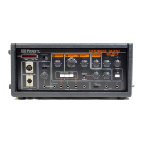
Details input/output levels, impedance, power consumption, dimensions, and weight for RE-501/SRE-555.

Arm Unit

Block Diagram

RE-501/SRE-555 Main Circuit Diagram

Adjustment and Checking

Mechanical Adjustments

Details procedures for physical adjustments like tape chassis position, height, and pinch roller pressure.

Electrical Adjustments

Covers various electrical calibration steps, including bias, playback, and head alignment.

Bias Leakage Trap

Motor Speed

Head Alignment Procedures

Tangency

Ensures head core faces are simultaneously tangent to the tape to the same degree.

Height

Centers gap-width dimension on the same track location.

Azimuth

Aligns head gap precisely 90-degrees to the tape edge.

Tilt

Ensures tape contacts head surface precisely in parallel.

Playback Heads Adjustments

Recording Adjustments

Expander and Echo Adjustments

Related product manuals