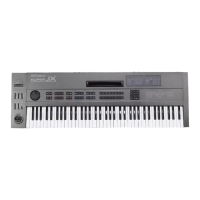
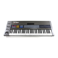
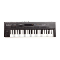
1.
Total Mix Output Jack
®
3. Output
Level Switch
Connect this to the
ampiifter. To make the best use
of
the JX-1
0,
use the amplifier
and speaker of wide
frequency
response and
dynamic range such as
keyboard
ampiifter.
2.
Parallel Output Jacks
®
These are also for
connecting amplifiers. Different
ways of connections
will make various sound
effects.
The following shows several different ways for
using
the Output Jacks.
PARALLB.
OUTPUT
tuoMx Huuen
(7)©©(^©
Connection
Jack Output Power
Uack
E Monaural Output
2 Jacks
A D Mixed Output of Upper
and Lower
B C B: Monaural Output of
Upper
C: Monaural Output of
Lower
A B
Stereo Output
of Upper
C D
Stereo
Output
of
Lower
4
Jacks
A B
C D
Stereo
Output
of Upper
and
Lower
When
the JX-10 is set to
the Whole mode,
connecting a stereo
amplifier
to
the UPPER
MONO
and
LOWER MONO of the Parallel
Out-
put Jacks 26 (output jacks C
and D
shown in
the above
picture)
will
cause
the sounds
to be
output irregularly through L or R. It is
normal
for this unit
to
behave like this.
Use
this switch
to select the output
level
depend-
ing on
the amplifier
connected to
the Total
Mix
Output.
*
This switch does
not work on the signal sent
from the Parallel
Output Jack.
4. Headphones Jack
®
Connect
stereo headphones
to this jack.
5. Hold Pedal Jack
®
By connecting the
optional pedal switch DP-6
or
DP-2,
the Hold effect
can be turned on or off
by
pressing
the pedal. "Hold" is
the effect of keeping
the sound even after
the key is released.
6. MIDI
Connector
®
This is for
connecting to other MIDI device
using
the MIDI/SYNC
cable (optionalj.
7. Programmer
Connector
Connect this to the programmer PG-SQO (optional)
using the supplied 6P
DIN cord.
8. Protect
Switch
®
Always
make sure that this switch is set to the
ON
position to protect
the data in the JX-10, except
when saving
or loading data.
9. Control Assign Jack
®
Use this jack when assigning
the
Control
Changes
with the expression
pedal or pedal switch.
 Loading...