JUN.
15,
1981
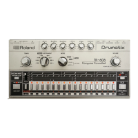
TR-808
START
ON
ANT I
LOG
Q16
POWER
ON
RESET
SWITCH
FIGURE 8 START/STOP
&
TEMPO
CLOCK
CIRCUITS
Start Sto
F
oiAiti/
oi
Uir
oiAlUo
Q12 collector
TEMPO
CLOCK
Q15
collector
ICl
pin 1
ICl
pin 2
IC2
pin
4
IC2
pin
6
ICl
pin
13
ICl
pin
12
X
Q16
ON
(charge)
FIGURE
9 TEMPO
CLOCK TIMING
DIAGRAM
START/STOP
& Tempo Clock
When the
power supply
for TR-808 is turned on, the TEMPO clock
continues
oscillation regardless
of the operation mode of
TR-808.
However,
when the
START button is pressed
in
the
STOP nnode,
oscfllation
stops once for
9ms
to
provide
a mode change preparation
time to
CPU. In this
way, the START/STOP
circuit and the TEMPO
circuit are closely related
with each other. When the
SYNC IN/OUT
switch
is set to IN,
both circuits become ineffective
and externaf
signals from
the DIN
socket duplicate the both
circuits.
When the_
START/STOP switch
is pressed (closed) with rhythm
stopped, Q
of F/F
IC2B
becomes L,nhe collector of
01 2
becomes
H, of
IC2B becomes
H
and
IC2A
is reset. Q of
IC2A
becomes
H
and
the
collector of
015 becomes
L.
Then,
since O of
IC2B
becomes
H, pin
2
of
ICl becomes
L
to turn
on
016.
As a
result, the TEMPO
GENERATOR of
2/4 ICl
(D,
E)
stops
oscillation
(details are de-
scribed later). After 9m$
later, pin
1
of
IC1A drops below the thresh-
old
level and pin
2
is
reversed. The rising edge reverses of
IC2A to
L
and the
collector of 015
(TEMPO CLOCK output) becomes
H.
At
the same time,
016 is cut off, and
CIO starts discharging through
the
ANTI-LOG 014
to continue oscillation.
This
discharging speed of
CIO determines the oscillation frequency
of
the TEMPO clock.
The variation
range is between 8.3ms and 65ms.
With TR-808,
J
is defined
to
have
24 clocks, and thus
I
is
approximately equal
to
400—300.
When
the level of
CIO exceeds the threshold level of pin
13
of
ICl
due
to discharging, the
output of pin 10 is reversed, 016
turns on,
and
CIO is charged. The output
of pin 12 of ICl is divided into
1/2
byT-FFof
IC2A.
^
=
rn
21LJ
R.l-e2-
C/-C2.
FIGURE
11
REPRESENTATIVE
BRIDGED
T-NETWORK
E^y
ELOPE
zz
OUT
-o
r
FIGURE
10
POWER
ON/OFF DETECTOR
HUTIK)^
Muting, Reset
The circuit
composed of 010—012
detects
power on/off
or
sharp
voltage drops
in
TR-808
DC
lines and feeds forward bias
(0
volts)
to
FET switches connected
to point
A.
These FETs are for resetting
CPU
(064),
preventing
writing into RAMs
(075)
and muting
Master
Out
(013).
Power
on : OV 1 -2sec
-
1 5
V
Power off:
-15VtoOV
If
this circuit
is defective,
the CPU may be kept reset. (Detail in
TROUBLESHOOTING on page
14.)
D
C3
^
FIGURE
12 REPRESENTATIVE
SWING TYPE
VCA
Sound Generators
The
bridged
T-network filter
shown in Fig.
11 is used
to
generate
periodic
damping
drum sound.
This configuration
has variations
according
to application
(instrument
sound). Values of
R and
C
can
be changed.
With this
circuit, the decay
time becomes longer
as
O
increases.
The
swing type
VCA shown in Fig.
12 is
used to generate metalic
sound
(noise). This
circuit features
its
output waveform having
many high
harmonic
components
to provide
ringing metalic sound.
Major features of
each
sound generator
are described
below.
Bass
Drum
This sound
generator
is
composed
of
a multi-feedback,
bridged
T-network
including
1/2 IC12 (pins 1-3)
as
an
active element. The
decay time
of the
resonating
waveforms
can
be controlled
by
ad-
justing
feedback
amount
by VR6.
Immediately
after
a trigger
pulse is
fed into
the
generator, the
filter's
time
constant
-
when
ACCENT is
present
-
is halved
and
has
a
resonance
on twice its
inherent
frequency
for
a
half
cycle period,
then
on the
fixed frequency
with
decaying
amplitude.
This
changing
frequencies
will sound
a punchier
crisp
bass. This trick
is performed
by the
circuit
composed
of 041—043.
When
a
trigger
signal
is
outputted
from
the collector
of
Q40, 041
turns on,
042 turns off,
043 turns on
and
R165 is shorted.
This
halves the
time constant
of this
network.
The
ON period of 043
is
determined
by
R156
and
C38 and
equals 4ms which
is
1/2 x
1/2
of
16ms
of
the
inherent
oscillation
period of the filter.
When
042
tgrns on after
4ms, current
discharging
from C39 via
R161
produces a retriggering
pulse. At
this time the
generator
oscil-
lates
on the
inherent
frequency.

 Loading...