33
May, 2007 V-SYNTH/GT
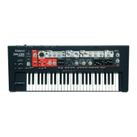
5. MAIN OUT
This tests the audio signal (L and R) output from the MAIN OUT connectors.
A screen like the one shown below is displayed on the LCD.
fig.05-mainout.eps_90
The audio signal input from the INPUT (L/R) connectors is output from the
MAIN OUT (L/R) connectors.
If no problem is encountered, press [ ] to advance to the next test item.
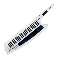
6. MAIN OUT (+12 dB)
This tests the audio signal (L and R) output from the MAIN OUT connectors.
A screen like the one shown below is displayed on the LCD.
fig.06-mainout12db.eps_90
The audio signal input from the INPUT (L/R) connectors is output from the
MAIN OUT (L/R) connectors at a higher volume than in “5. MAIN OUT.”
If no problem is encountered, press [ ] to advance to the next test item.
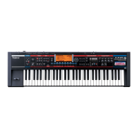
7. DIRECT OUT
This tests the audio signal (L and R) output from the DIRECT OUT connectors.
A screen like the one shown below is displayed on the LCD.
fig.07-directout.eps_90
The audio signal input from the INPUT (L/R) connectors is output from the
DIRECT OUT (L/R) connectors.
If no problem is encountered, press [ ] to advance to the next test item.
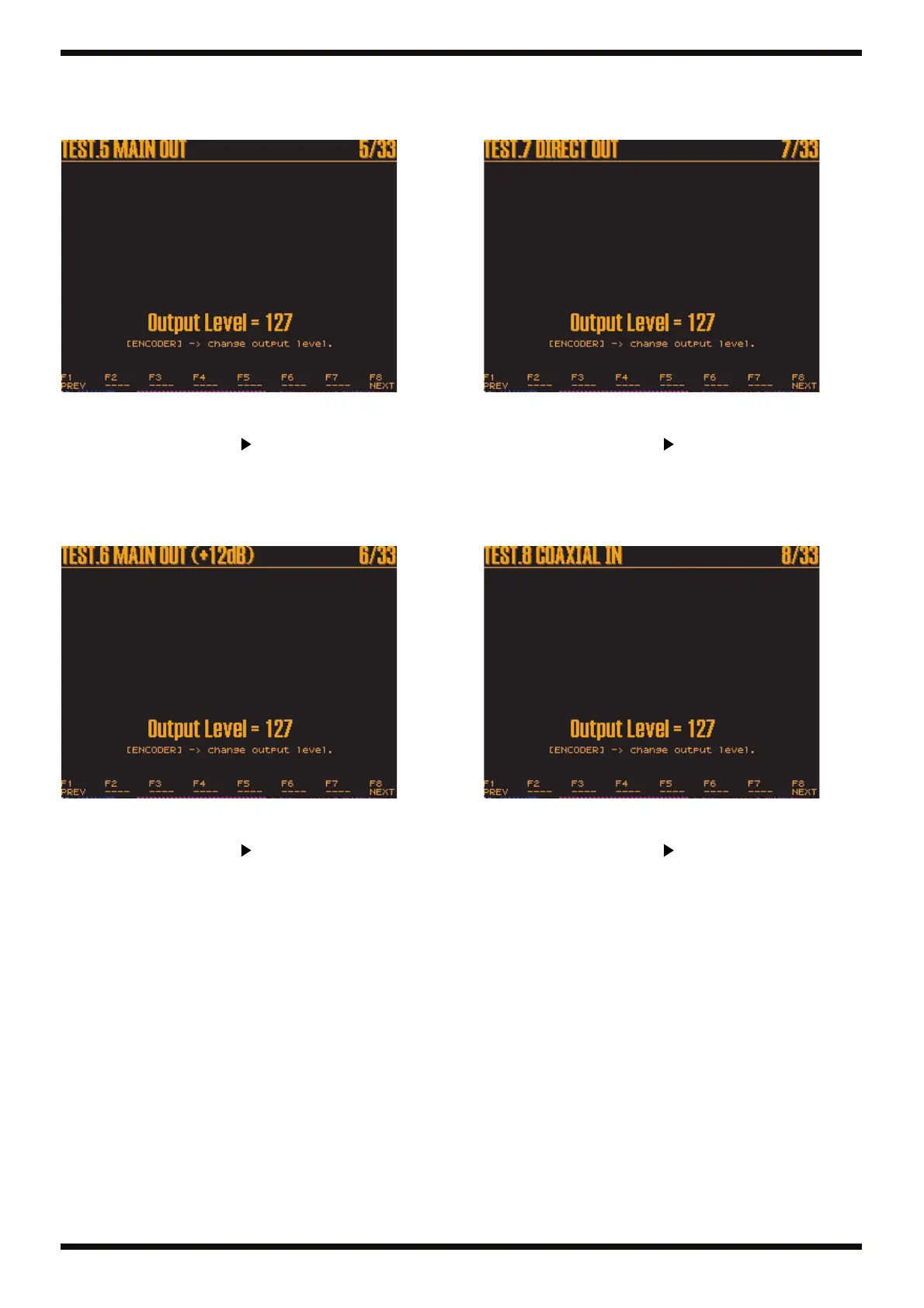
8. COAXIAL IN
This tests the audio signal input from the COAXIAL IN connector.
A screen like the one shown below is displayed on the LCD.
fig.08-coaxin.eps_90
The audio signal input from the COAXIAL IN connector is output from the
MAIN OUT (L/R) connectors.
If no problem is encountered, press [ ] to advance to the next test item.
 Loading...