34
May, 2007 V-SYNTH/GT
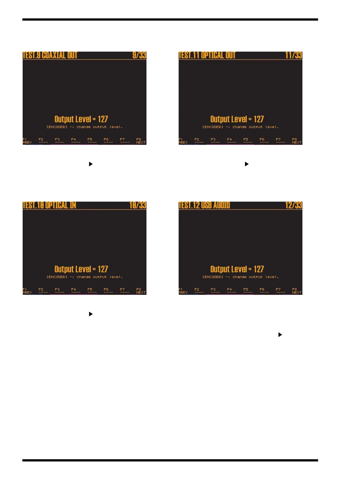
9. COAXIAL OUT
This tests the audio signal output from the COAXIAL OUT connector.
A screen like the one shown below is displayed on the LCD.
fig.09-coaxout.eps_90
The audio signal input from the LINE IN (L/R) connectors is output from the
COAXIAL OUT connector.
If no problem is encountered, press [ ] to advance to the next test item.
10. OPTICAL IN
This tests the audio signal input from the OPTICAL IN connector.
A screen like the one shown below is displayed on the LCD.
fig.10-optin.eps_90
The audio signal input from the OPTICAL IN connector is output from the
MAIN OUT (L/R) connectors.
If no problem is encountered, press [ ] to advance to the next test item.
11. OPTICAL OUT
This tests the audio signal output from the OPTICAL OUT connector.
A screen like the one shown below is displayed on the LCD.
fig.11-optout.eps_90
The audio signal input from the LINE IN (L/R) connectors is output from the
OPTICAL OUT connector.
If no problem is encountered, press [ ] to advance to the next test item.
12. USB AUDIO
This tests the audio signal input from the USB COMPUTER connector.
A screen like the one shown below is displayed on the LCD.
fig.12-usbaudio.eps_90
Play back any WAVE file on the computer.
* A number of sample WAVE files can be found in C:\WINDOWS\Media.
The audio signal input from the USB COMPUTER connector is output from
the MAIN OUT (L/R) connectors.
If no problem is encountered, stop playback and press [ ] to advance to the
next test item.
 Loading...