MAR, 2000 XV-88
13
•
When a sound is outputted, the number of the outputting terminal goes out.
•
Pressing [1/9] through [4/12] selects the outputting terminal directly.
In case the sound is not outputted correctly, check the following com-
ponent depending on the outputting terminal.
If not sound is outputted;
From all terminals : check IC53 through 55, IC59, IC61, Q31
through 34, and CN18 on the main board.
From OUTPUT 1,2 & Headphone L,R
:
check IC53, IC55 and CN18 on the main
board, CN1, CN2 and IC1 on the analog
board, and CN2, VR5, C3, C7 and IC3
on the panel A board.
From OUTPUT 1,2 : IC3, C15, C22 ,C29, C36, Q3 through 6, JK2
and JK3 on the analog board
Only from OUTPUT 1 :
C15, C22, Q3, Q4 and JK2 on the analog board
Only from OUTPUT 2 :
C29, C36, Q5, Q6 and JK3 on the analog board
From Headphone L,R :
IC4, C4, C10, Q1, Q2 and JK1 on the analog board
Only from Headphone L
: C4, Q1and JK1 on the analog board
Only from Headphone R
: C10, Q2 and JK1 on the analog board
From OUTPUT 3,4 : IC2, C45, C53, Q7, Q8, JK4 and JK5 on the
analog board
Only from OUTPUT 3 : C45, Q7 and JK4 on the analog board
Only from OUTPUT 4 : C53, Q8 and JK5 on the analog board
•
When "OUTPUT 4" is confirmed, pressing [ENTER] key moves the
test item to the next one.
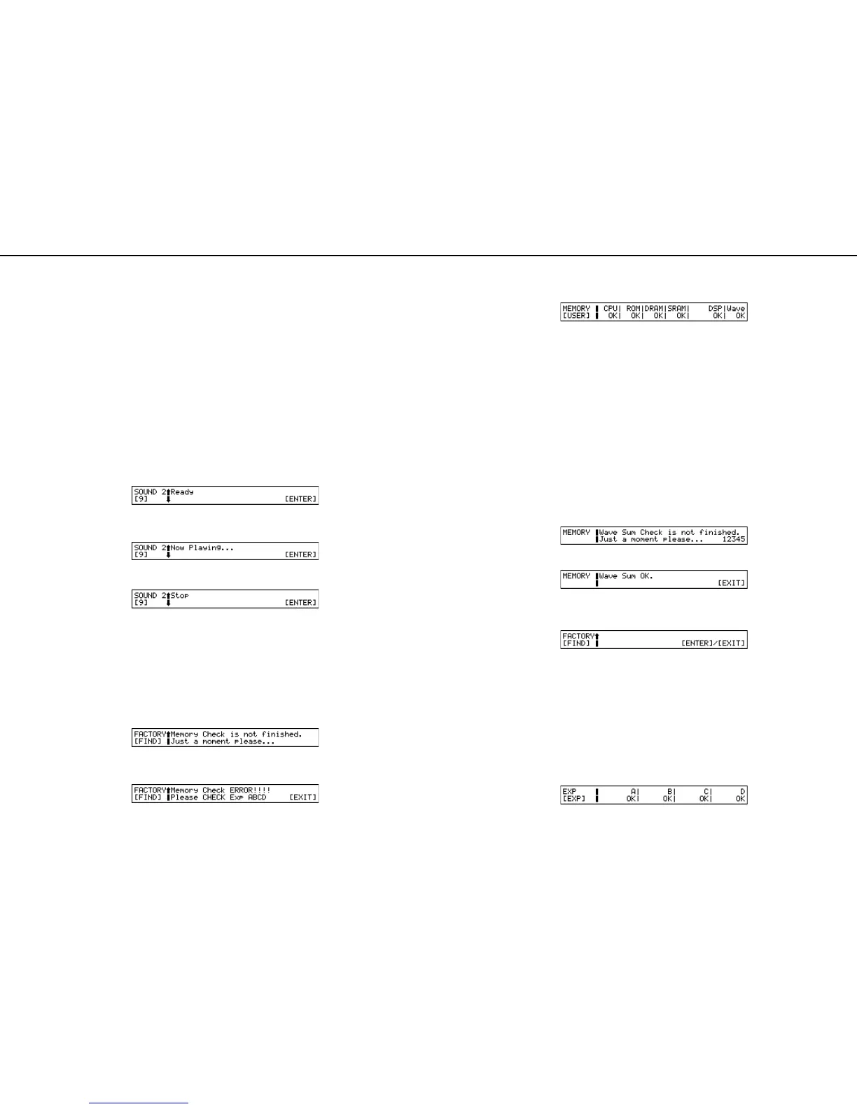
11 : Sound Test 2
*fig_test19
•
Press [ENTER] key to start the test sound generation.
•
The sound generated can be confirmed with Monitor speaker or Headphone.
*fig_test20
•
Press [ENTER] key to stop the test sound generation.
*fig_test21
In case no sound is outputted or the sound will not stop, check IC53,
55 and CN18 on the main board, CN1, CN2 and IC1 on the analog
board, and CN2, VR5, C3, C7 and IC3 on the panel A board.
•
When the test is completed, pressing [ENTER] moves the test item
once to the top page and then to "1.MIDI Test", and when the tests are
performed consecutively, the memory checks of 12 and 13 are per-
formed automatically.
When selecting a test without going through the test items consecu-
tively, the memory check is not performed, and the test items moves to
"14. Factory Reset".
•
During the automatic memory check, the following screen appears.
(This screen does not appear if the memory check is already completed.)
*fig_test22
•
In case even one abnormality is detected in the memory check, the fol-
lowing screen appears where the location of the abnormality is shown.
*fig_test23
In such case, select the test of 12 and 13 directly to check the location of
the abnormality.
•
When no abnormality is detected in the memory check, the test item
moves to "14. Factory Reset".
12 : Memory Test
•
Check CPU-RAM/ROM, Program ROM, DRAM, SRAM, WAVE
ROM and XP-DSP/RAM.
CPU: OK RAM and ROM of CPU are normal.
NG Abnormal. Check IC4 and IC2 on the main board.
ROM: OK Program ROM is normal.
NG
Abnormal. Check IC2, RA16 and RA21 on the main board.
DRAM: OK DRAM is normal.
NG Abnormal. Check IC5 and RA16 on the main board.
SRAM: OK SRAM is normal.
NG Abnormal. Check IC6, IC7, RA16 and RA21 on the
main board.
DSP: OK Both DSP and RAM of XP are normal.
I0-NG Internal RAM of XP0 is abnormal. Check IC16 and
IC73 on the main board.
I1-NG Internal RAM of XP1 is abnormal. Check IC17 and
IC73 on the main board.
E0-NG External RAM of XP0 is abnormal. Check IC20 on
the main CPU.
E1-NG External RAM of XP1 is abnormal. Check IC21 on
the main board.
Wave: OK Wave ROM is normal
NG
Abnormal. Check IC23 and IC27 on the main board.
•
When the results of all the tests are "OK", the following screen
appears, and calculation of entire memory checksum of Wave ROM
is performed automatically.
When the value of checksum of Wave ROM is correct, the following
screen appears.
If it is incorrect, check IC23 and IC27 on the main board.
•
Press [EXIT] key to return to the top page.
13 : Expansion Board Test
•
Before performing this test, it is necessary to install the wave expan-
sion boards in all slots.
At this time, before installing the wave expansion boards, turn off the
power supply, install the boards, and then enter the TEST MODE again.
If the boards are installed with the power supply turned on, the
board cannot be read correctly, and the board may be damaged.
•
Individual slots are checked automatically.
A/B/C/D : OK Normal
NG Abnormal.
Check the components as follows depending on the slots showing "NG".
A/B :
IC6, IC10, IC11 RA26, CN1, CN2, CN5 and CN6 on the EXP base board
C/D : IC1 through 8, RA1, RA5, RA7, RA10, RA12, RA24, CN1 and
CN2 on the EXP base board.
•
Press [EXIT] key to return to the top page..
13 : Factory Reset
•
Press [VALUE] key to perform factory reset.
* Be sure to perform the factory reset at the end of the TEST MODE.
•
Press [EXIT] key to return to the top page..
•
Press [EXIT] key on the top page closes the TEST MODE.
・ サウンドが出力されると、出力先の番号が消えます。
・ [1/9] - [4/12] を押すと出力先を直接選択できます。
音が正しく出力されない場合は、その出力先によって以下の個所を
チェックして下さい。
全て出力されない : メインボード
IC53 ~ 55,IC59,IC61,Q31~34,CN18
OUTPUT 1,2 & ヘッドホン L,R : メインボード IC53,IC55,CN18, ア
ナログボード CN1,CN2,IC1, パネ
ル A ボード
CN2,VR5,C3,C7,IC3
OUTPUT 1,2 : アナログボード
IC3,C15,C22,C29,C36,Q3 ~ 6,JK2,JK3
OUTPUT 1 のみ : アナログボード C15,C22,Q3,Q4,JK2
OUTPUT 2 のみ : アナログボード C29,C36,Q5,Q6,JK3
ヘッドホン L,R : アナログボード IC4,C4,C10,Q1,Q2,JK1
ヘッドホン L のみ : アナログボード C4,Q1,JK1
ヘッドホン R のみ : アナログボード C10,Q2,JK1
OUTPUT 3,4 : アナログボード IC2,C45,C53,Q7,Q8,JK4,JK5
OUTPUT 3 : アナログボード C45,Q7,JK4
OUTPUT 4 : アナログボード C53,Q8,JK5
・ OUTPUT 4 の出力の確認をし、[ENTER] を押すと、次のテスト項目に
なります。
11 : Sound Test 2
・ [ENTER] を押すとテスト発音を開始します。
・ 出力される音をモニタースピーカーまたはヘッドホンで確認します。
・ [ENTER] を押すとテスト発音を停止します。
音が出力されない、または停止しない場合、メインボード
IC53,55,CN18, アナログボード CN1,CN2,IC1, パネル A ボード
CN2,VR5,C3,C7,IC3 をチェックして下さい。
・テストを完了し、[ENTER] を押すと、トップページから 1.MIDI TEST
に入り、順にテストを行ってきた場合、ここで自動的に12,13 の各
種メモリチェックを行います。
テストを順に行わず、直接テストを選択して行った場合は、メモリ
チェックは行わず、14.Factory Reset へ進みます。
ÅE
・ 自動的にメモリチェックを行っている間、以下のような画面になり
ます。(メモリチェックがすでに終了している場合は、この画面表示
は出ません。)
・ メモリチェックに1つでも異常があった場合、以下のような画面に
なり、NG の箇所が示されます。
この場合 12,13 のテストを直接選択して行い、NG の箇所をチェックし
て下さい。
・ メモリチェックで異常がない場合、そのまま 14.Factory Reset に
進みます。
12 : Memory Test
・ CPU-RAM/ROM, Program ROM, DRAM, SRAM, WAVE ROM, XP-DSP/RAM を
チェックします。
CPU: OK CPU の RAM と ROM は正常です。
NG
異常です。メインボードの IC4,IC2 をチェックして下さい。
ROM: OK Program ROM は正常です。
NG 異常です。メインボードの IC2,RA16,RA21 をチェッ
クして下さい。
DRAM: OK DRAM は正常です。
NG
異常です。メインボードの IC5,RA16 をチェックして下さい。
SRAM: OK SRAM は正常です。
NG 異常です。メインボードの IC6,IC7,RA16,RA21 を
チェックして下さい。
DSP: OK XP の DSP と RAM はすべて正常です。
I0-NG XP0 の内部 RAM が異常です。メインボードの
IC16,IC73 をチェックして下さい。
I1-NG XP1の内部 RAM が異常です。メインボードの
IC17,IC73 をチェックして下さい。
E0-NG XP0 の外部 RAM が異常です。メインボードの IC20 を
チェックして下さい。
E1-NG XP1の外部RAM が異常です。メインボードの IC21 を
チェックして下さい。
Wave: OK Wave ROM は正常です。
NG
異常です。メインボードの IC23,IC27 をチェックして下さい。
・ テストが全て OK の場合 以下のような画面になり、自動的に Wave
ROM の全メモリチェックサムの計算を行います。
Wave ROM のチェックサムが正しい値であれば、以下のような画面に
なります。
NG の場合にはメインボードの IC23,IC27 をチェックして下さい。
・ [EXIT] を押すと、トップぺージに戻ります。
13 : Expansion Board Test
・ この項目に入る前にあらかじめウェーブエクスパンションボード
をすべてのスロットに装着しておく必要があります。
この時点でウェーブエクスパンションボードを装着する場合は、
一度電源を切ってボードを装着し、再度テストモードに入ってく
ださい。電源を入れたまま装着すると、ボードを正しく読み取る
ことが出来ません。また、ボードが壊れる可能性があります。
・ 各スロットを自動的にチェックします。
A/B/C/D : OK 正常です。
NG 異常です。
NG のスロットによって以下の個所をチェックして下さい。
A/B : EXP ベースボード IC6,IC10,IC11,RA26,CN1,CN2,CN5,CN6
C/D : EXP ベースボード
IC1~8,RA1,RA5,RA7,RA10,RA12,RA24,CN1,CN2
・ [EXIT] を押すとトップページに戻ります。
13 : Factory Reset
・ [VALUE] を押すとファクトリーリセットを実行します。
※ テストモードの最後には必ずファクトリーリセットを行ってください。
・ [EXIT] を押すとトップページに戻ります。
・ トップページで [EXIT] を押すと、テストモードを終了します。
 Loading...