XV-88 MAR, 2000
10
TEST MODE
Items required
•
Audio cable 1 through 4 pieces
•
MIDI Cable 1 piece
•
Computer test cable (#17049906) 1 piece
•
SmartMedia 2 pieces
(Formatted, and protected and unprotected respectively)
•
Expression pedal
•
Monitor speaker (MA-12 etc.)
•
Head phone
•
Oscilloscope
•
D beam adjustment jig (plate of approximately 18 cm square)
•
40 centimeters measurable scale
•
Wave expansion board SR-JV80 series 2 pieces
•
Wave expansion board SRX Series 2 pieces
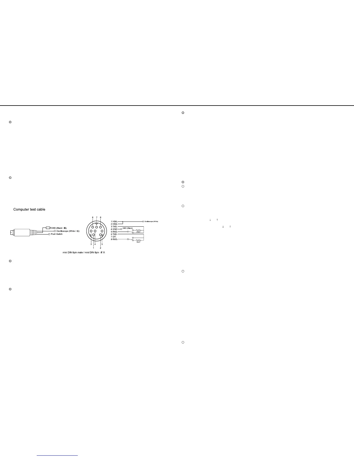
Computer test cable
"Computer test cable" (17049906) is required to perform Computer I/F
Test in TEST MODE.
3rd pin and 5th pin, and 6th pin and 8th pins of this cable which are
male mini DIN 8 pins are connected respectively. 1st pin outputs the
waveform, and 4th pin is used as GND.
When this component is needed, please give your order to the Roland
service center.
*fig_test1
D beam adjustment jig
(plate of approximately 18 cm square)
This jig is needed to perform D beam adjustment in TEST MODE. The
plate must meet the following requirements.
1. Dimensions:18 X 18 centimeters (tolerance: ± 1 centimeter)
2. Thickness: Not specified
2. Color:
Grey (non-lustrous) some characters written are acceptable.
3. Material: Not specified (paper is acceptable.)
Precautionary notes
•
User data may be erased when entering TEST MODE.
Be sure to make backup data.
•
Do not insert or eject the SmartMedia with power supply turned on,
or the SmartMedia may be damaged.
Be sure to turn off the power supply before inserting or ejecting the
SmartMedia.
•
The contents of SmartMedia are lost when card test it performed.
Use the SmartMedia for test when performing the card test.
•
Install the wave expansion board on the unit before turning on the
power supply.
The board may be damaged if it is installed with the power supply
turned on.
•
Set the computer slide switch on the rear to "MAC" before turning on
the power supply.
If the switch is not at this position, the computer interface cannot be
tested correctly.
Test items
XV-88 provides the following test.
For the details of individual test, refer to their respective sections.
0 : Top Page
(Identifying the version number, Battery check, and Memory card check)
1:MIDI Test
2:A/D Test
3 : D Beam Adjustment
4 : Bender / D Beam Test
5:After touch Test
6 : Switch & LED Test
7 : LCD & Encoder Test
8 : Computer I/F Test
9 : Card Test
10: Sound Test 1
11 : Sound Test 2
12: Memory Test
13: Expansion Board Test
14: Factory Reset
Operations of keys
How to enter TEST MODE
•
Confirm that the computer slide switch on the rear is at "MAC".
•
Turn on the power while pressing [EXIT].
•
Pressing [UNDO/COMP] key while the opening message is displayed
enables TEST MODE where the Top page appears.
Changing test item
•
Pressing [ENTER] on the top page changes the test item to "1. MIDI Test".
•
For test items 1 through 8, successful ending of individual test
changes the item to next one automatically.
•
Pressing a cursor key [ ] or [ ] during a test can change the item to
the next one or previous one even if the test is not completed.
* For "6. Switch & LED test", press [ ] or [ ] key while pressing
[SHIFT] key..
•
Pressing [EXIT] key returns the item to top page in a TEST MODE.
* For "6. Switch & LED test", Pressing [EXIT] while pressing [SHIFT]
returns the item to top page.
•
When the tests are completed consecutively from the top page and
"11. Sound Test 2" is completed, memories are checked automatically
in the items 12 and 13.
* When all the tests are performed successfully, the step moves to
"14. Factory Reset".
For the details of the display, refer to the description of test items in the
latter part of this document.
Jumping to another test item
Pressing a key such as a numerical key while pressing and holding
[SHIFT] selects a test item corresponding to the number directly as
described below.
0 : [SHIFT]+[EXIT] Top Page
1 : [SHIFT]+[1] MIDI Test
2 : [SHIFT]+[2] A/D Test
3 : [SHIFT]+[D BEAM] D Beam Adjustment
4 : [SHIFT]+[3] Bender / D BEAM Test
5 : [SHIFT]+[4] After touch Test
6 : [SHIFT]+[5] Switch & LED Test
7 : [SHIFT]+[6] LCD & Encoder Test
8 : [SHIFT]+[7] Computer I/F Test
9 : [SHIFT]+[CARD] Card Test
10 : [SHIFT]+[8] Sound Test 1
11 : [SHIFT]+[9] Sound Test 2
12 : * [SHIFT]+[USER] Memory Test
13 : * [SHIFT]+[EXP] Expansion Board Test
14 : [SHIFT]+[PATCH FINDER] Factory Reset
* When the test items are selected consecutively from the top page, the
memory test of items 12 and 13 are not performed automatically at the
completion of "11. Sound Test 2".
How to exit TEST MODE
Return to the top page and press [EXIT] key.
テストモード
テストモードテストモード
テストモード
◎準備するもの
◎準備するもの◎準備するもの
◎準備するもの
・ オーディオケーブル 1~4 本
・ MIDI ケーブル 1 本
・ コンピューターテストケーブル(#17049906)1本
・ スマートメディア 2 枚
(フォーマット済みのもので プロテクトされているもの、プロテク
トされていないもの 各 1 枚ずつ)
・ エクスプレッションペダル
・ モニタースピーカー (MA-12 etc.)
・ ヘッドフォン
・ オシロスコープ
・ D ビーム調整治具 ( 約 18cm 四方の板)
・ 40 センチが計れるメジャー
・ ウェーブエクスパンションボード SR-JV80 シリーズ 2 枚
・ ウェーブエクスパンションボード SRX シリーズ 2 枚
◎コンピュータテストケーブルについて
◎コンピュータテストケーブルについて◎コンピュータテストケーブルについて
◎コンピュータテストケーブルについて
テストモードで Computer I/F Test を行う際には、"Computer test
cable"(17049906) が必要です。
これは、mini DIN 8pin オスの 3 ピンと 5 ピン、6 ピンと 8 ピンがそ
れぞれショートされ、1 ピンから波形を出力し、4 ピンから GND をと
る構造になっています。
必要な場合には、ローランドサービスセンターまでオーダーしてください。
◎ D ビーム調整治具 ( 約 18cm 四方の板)
◎ D ビーム調整治具 ( 約 18cm 四方の板)◎ D ビーム調整治具 ( 約 18cm 四方の板)
◎ D ビーム調整治具 ( 約 18cm 四方の板)
テストモードで D ビーム調整を行う際に必要です。板の条件は、以下
の通りです。
1. 大きさ:
18 センチ× 18 センチ(± 1センチぐらいは、問題ありません)
2. 厚さ : 特に指定はありません。
2. 色 :グレー(光沢がない物)多少文字などが記載されていても
可。
3. 材質 : 指定は、ありません(紙でも可)
◎テストを始める前の注意
◎テストを始める前の注意◎テストを始める前の注意
◎テストを始める前の注意
・ テストモードに入るとユーザーデータは消去される場合がありま
す。必ずデータのバックアップを行って下さい。
・電源を入れたまま スマートメディアの抜き差しを行うと、スマー
トメディアが壊れる可能性があります。抜き差しの際は必ず電源
を切って下さい。
・ カードテストを行うと、スマートメディアの内容は失われてしま
います。テスト用のスマートメディアを準備し、使用して下さい。
・ ウェーブエクスパンションボードは電源を入れる前にあらかじめ
本体に装着して下さい。電源を入れたまま装着すると、ボードが
壊れる可能性があります。
・電源を入れる前にリア面のコンピュータのスライドスイッチを Mac
にしておきます。この状態でないと コンピューター・インター
フェース のテストが正しく行われません。
◎テスト項目
◎テスト項目◎テスト項目
◎テスト項目
XV-88 には以下のテストがあります。
各テストの詳細については、それぞれの項目を参照して下さい。
0 : Top Page
(Identifying the version number,Battery check,Memory card check)
1:MIDI Test
2:A/D Test
3 : D Beam Adjustment
4 : Bender / D Beam Test
5 : Aftertouch Test
6 : Switch&LED Test
7 : LCD&Encoder Test
8 : Computer I/F Test
9 : Card Test
10: Sound Test 1
11 : Sound Test 2
12: Memory Test
13: Expansion Board Test
14: Factory Reset
◎ボタン操作
◎ボタン操作◎ボタン操作
◎ボタン操作
○ テストモードへの入り方
・リア面のコンピュータのスライドスイッチを Mac にしておきます。
・ [EXIT] を押しながら電源を入れます
・ オープニング・メッセージ表示中に [UNDO/COMP] を押すと、テス
ト・モードに入りトップ・ページを表示します。
○各テスト項目の移動
・ トップ・ページで [ENTER] を押すと、テスト項目 1.MIDI TEST に移
ります。
・ テスト項目 1~8 は 各テストが正常に終了すると、自動的に次のテ
スト項目に移ります。
・カーソル [ ↓ ]/[ ↑ ] を押すと、テストが終了していなくても 次の
テスト項目 / 一つ前のテスト項目 に移動します。
※ 6.Switch&LED test では [SHIFT] と [ ↓ ] または [ ↑ ] の2つ
のボタンを押します。
・ 各テストモードで [EXIT] を押すとトップページになります。
※ 6.Switch&LED Test では、[SHIFT][EXIT] の 2 つのボタンを押す
とテスト・モードのトップ・ページに戻ります。
・ トップページから順にテストモードを進め 11.Sound Test 2 を終了
すると、12,13 の各種メモリチェックが自動的に行われます。
※ チェックで NG がない場合は、14.Factory Reset に移ります。
画面表示の詳細は、後述の テスト項目詳細 を参照して下さい。
○各テストへのジャンプ
[SHIFT] を押しながら テン・キー 等を押すと対応するテスト項目を直
接選択できます。
0 : [SHIFT]+[EXIT] Top Page
1 : [SHIFT]+[1] MIDI Test
2 : [SHIFT]+[2] A/D Test
3 : [SHIFT]+[D BEAM] D Beam Adjustment
4 : [SHIFT]+[3] Bender / D BEAM Test
5 : [SHIFT]+[4] Aftertouch Test
6 : [SHIFT]+[5] Switch&LED Test
7 : [SHIFT]+[6] LCD&Encoder Test
8 : [SHIFT]+[7] Computer I/F Test
9 : [SHIFT]+[CARD] Card Test
10 : [SHIFT]+[8] Sound Test 1
11 : [SHIFT]+[9] Sound Test 2
12 : * [SHIFT]+[USER] Memory Test
13 : * [SHIFT]+[EXP] Expansion Board Test
14 : [SHIFT]+[PATCH FINDER] Factory Reset
* トップページからこの方法でテスト項目を選択した場合、12,13 の各
種メモリーのテストは、11.Sound Test 2 の終了時、自動的に行われ
ません。
○ テストモードからの抜け方
トップページに戻り [EXIT] を押します。
 Loading...