Product Specification
BasicCharge Intelligent EV Charging Pedestal EVBM-V01-R1 Installation and Operation Manual
Page 11 of 36 December 2022
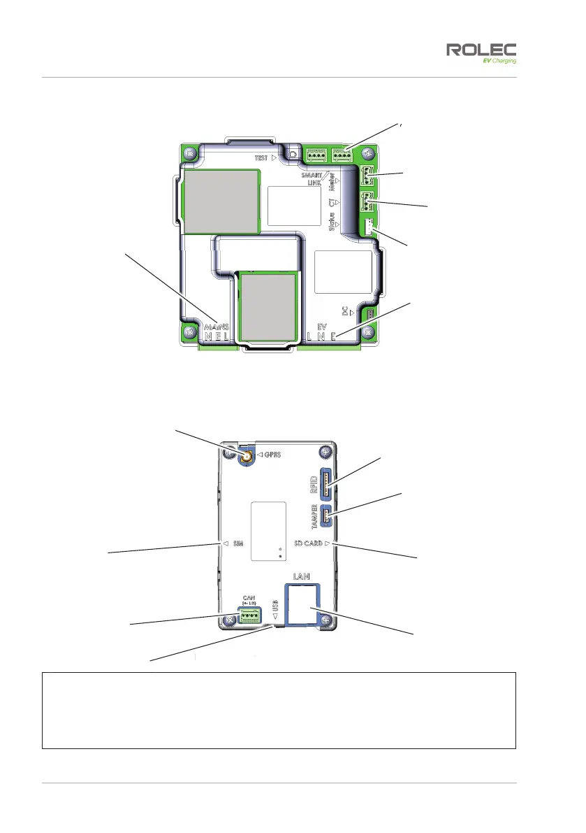
Figure 4 EV Charge Controller
Figure 5 Smart Communications Module
NOTE:
x The EV Charge Controllers are located within the enclosure on the same side as the
sockets.
x The Smart Communications Module is located within the other side of the enclosure.
x The RFID sensor is located within the enclosure on the same side as the RFID plate.
CANBUS
Connector
Connection to
Anti-Tamper Devices
SD Card Location
RJ45 LAN
Connector
Connection to RFID
Board
USB Connector
ure
mart
GPRS Antenna
Connection
SIM Card
Location
Meter Connector
2x CT
Connectors
Status Indicator
‘Halo’ Connector
Smart Link
Connection
Power ‘OUT’ and
Signal Connector
to Socket
L, N, E.
Power ‘IN’
Connector to
PCB
N, E, L.