ROPE INNOVATION CO., LTD. CONFIDENTIAL NO.
:
ROPE-15121802
Copyright © 2016 ROPE INNOVATION CO., LTD. All rights reserved. Website: www.ropetrack.com
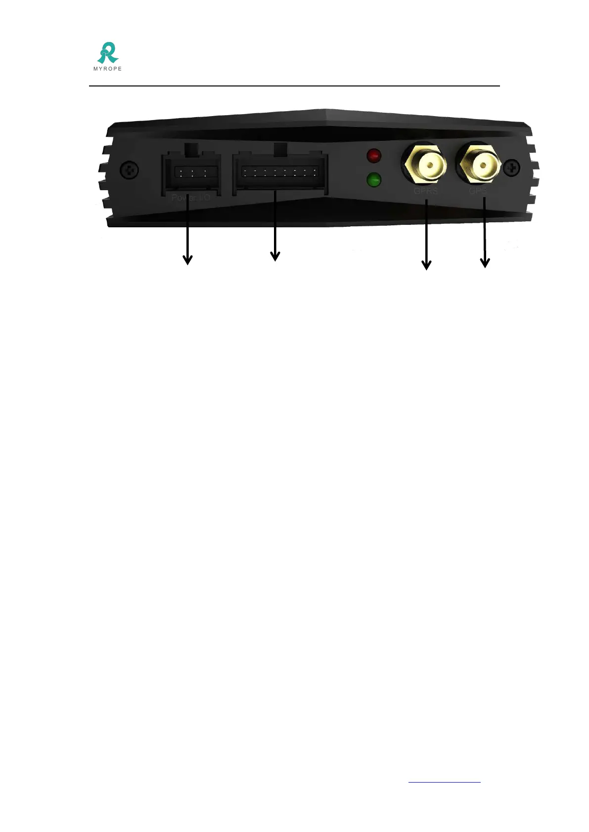
2.3 Device wiring diagram
Power I/O Extend GPRS GPS
Connector Connector Antenna
Antenna
Power I/O Connector:
1. Black and purple cables for microphone
5. Yellow cable for relay(from relay to tracker: yellow to yellow, black to black)
Extend Connector:
1. The first row:
1st cable to power+ of camera
2nd cable to GND
3rd cable to RX of fuel sensor
4th cable is for >5V high voltage detection
5th cable is for >5V high voltage output
6th cable is for >5V high voltage output
7nd cable to GND
8nd cable to power+ of speaker
2. The second row:
1st cable to TX of camera
2nd cable to RX of camera
3rd cable to TX of fuel sensor
4th cable is for AD input
5th cable is for <5V low voltage detection
6th cable to TX of RFID reader
7nd cable is RX of RFID reader
8nd cable to power- of speakerThe 8nd cable to power- of speaker