Do you have a question about the Ropex CIRUS UPT-6011 and is the answer not in the manual?
Compliance with DIN EN, EMC, and RoHS directives for controller functionality.
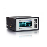
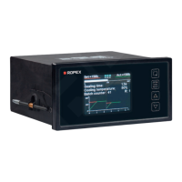
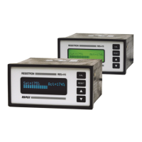
Controller measures current/voltage to adjust heating current for precise temperature control.
Step-by-step guide to installing the CIRUS Temperature Controller UPT-6011.
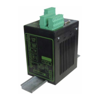
Standard wiring diagram showing connections for UPT-6011, impulse transformer, and current transformer.
Instructions for configuring the controller via coding switches and slide switches.
Procedure and safety for replacing the heating element, including AUTOCAL.
Rules and procedures to follow during the commissioning phase.
Step-by-step guide for the first-time startup of the controller.
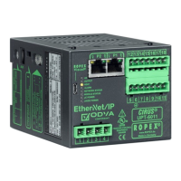
Communication via EtherNet/IP requires 24 VDC supply and line voltage.
Structure of input/output data for EtherNet/IP communication.
Automatic adjustment of zero point without manual intervention; procedure and conditions.
Enables set/actual comparison and heating; conditions for processing start requests.
Resets controller faults; conditions for accepting reset and subsequent initialization.
Defines the structure and services for device parameters.
Setting temperature range and heating element alloy, overwriting rotary switch.
Function to determine and correct temperature coefficient (TCR) of heating element.
Adapting controller to machine conditions via correction factor.
Provides web-based access to status information and parameters.
Displays stored absolute calibration resistances and deviation values.
USB interface for system diagnostics and process visualization.
Provides descriptions and corrective actions for various error codes.
Lists error codes, causes, and actions for faults.
Lists error codes, causes, and actions for warnings.
Lists more error codes, causes, and actions for warnings.
Helps to quickly identify and resolve specific fault areas.
| Brand | Ropex |
|---|---|
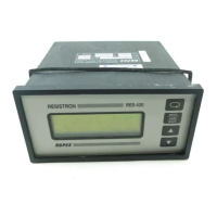
| Model | CIRUS UPT-6011 |
| Category | Temperature Controller |
| Language | English |