3
1. GENERAL DESCRIPTION
1.1 Description of the machine
- Hydraulic wheel free jack with mechanical stop (Fig. 1)
1.2 Purpose of the machine
The wheel free jack is designed to support and lift vehicles which are already supported on a specially
designed lift. The maximum load is indicated on the serial plate and corresponds to the maximum capacity of
the wheel free jack. Always contact the manufacturer’s technical services department for information on the
compatibility of this wheel free jack with the lift on which it is to be used and for the installation procedure.
1.3 Wheel free jack controls
A - Mechanical stop
B - Elevation pedal for pneumatic-hydraulic model
1.4 Main technical specifications
- Overload safety valve
- Sliding rollers for positioning wheel free jack on lift
- Mechanical device to avoid load casual descent.
*Specifications are subject to change without notice.
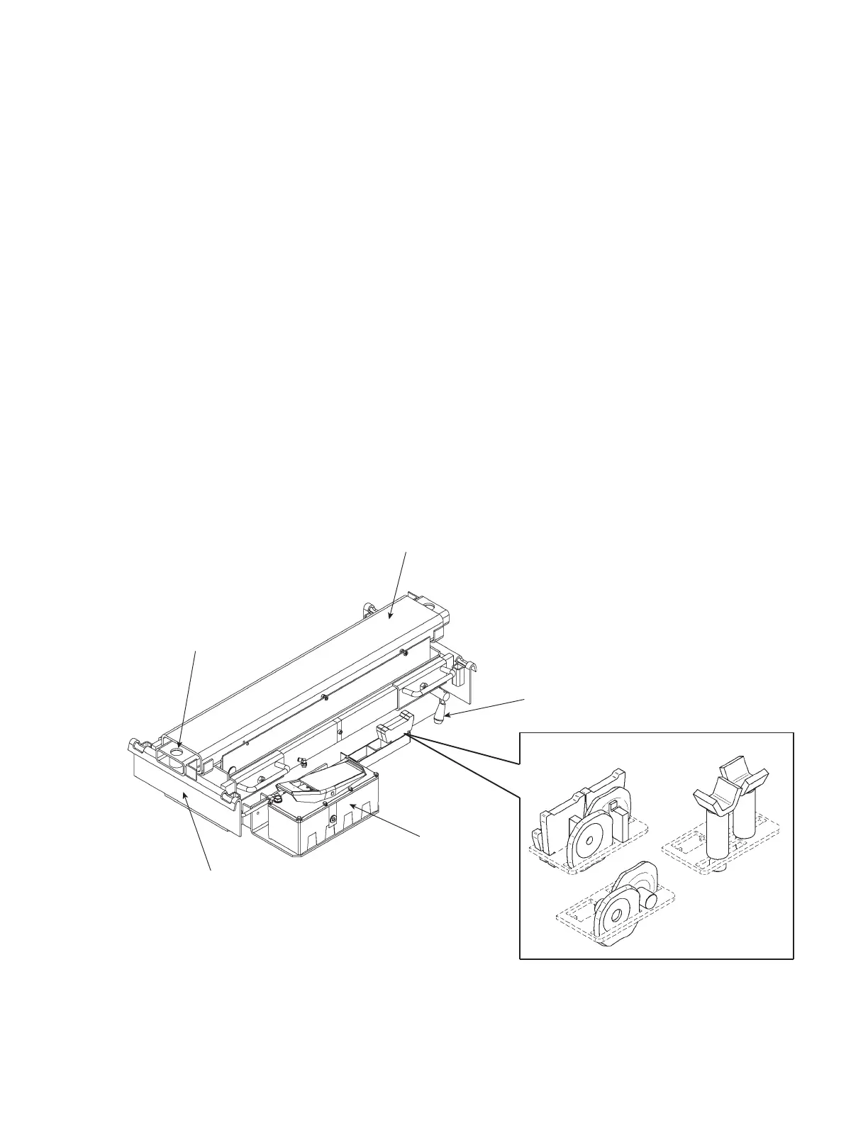
Fig. 1
B
Buffer Support
A
Lifting platform
Wheel Free Jack
Support Plate
Single Extension
Buffer Support
(55" 1/4 - 1400 mm)
 Loading...