Do you have a question about the Rotel RKB-650 and is the answer not in the manual?
Covers risk of electric shock, fire, moisture, ventilation, placement, power cord, and accessory use guidelines.
Details warnings for qualified service, installation, wiring, and when to seek professional help.
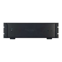
Describes the power switch, indicator LED, protection, and level adjustment controls on the front.
Explains the AC power input connector and circuit breaker located on the rear panel.
Identifies speaker terminals, input/output links, and 12V trigger connections on the rear.
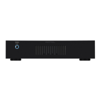
Highlights key capabilities like 50W/ch output, rack-mountability, and auto power-on.
Advises reading the manual, saving packaging, and keeping the sales receipt for warranty.
Provides recommendations for placing the amplifier to ensure proper cooling and prevent damage.
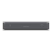
Details how to install the amplifier using rack mounting brackets and screws.
Explains the process of installing or removing rack handles for the unit.
Discusses the benefits and installation of an optional fan kit for enhanced cooling.
Guides on connecting the AC power cord to the unit and outlet, and unplugging when away.
Explains the function of the front panel power switch and its associated indicator LED.
Describes the three modes for automatic power management: OFF, SIGNAL SENSE, and 12V TRIG.
Details how to use the 12V trigger connections for remote power control with other components.
Explains the use of RCA inputs for connecting audio sources like preamplifiers or processors.
Describes how to link inputs for multiple channel groups, enabling shared stereo signals.
Guides on using front panel controls to adjust amplifier gain for system matching.
Explains how to pass input signals to other audio components for daisy-chaining.
Specifies the minimum speaker impedance and effects of parallel connections.
Advises on choosing appropriate wire gauge and type for optimal audio performance.
Emphasizes consistent polarity for all speaker and amplifier connections for correct phase.
Provides detailed instructions on connecting speaker wires using various connector types.
Guides on diagnosing issues when the front panel power indicator is not illuminated.
Offers steps to resolve problems when the amplifier produces no sound.
Explains how to address situations where the protection indicators are lit, suggesting causes and reset procedures.
| Purpose | - |
|---|---|
| Product color | Black |
| Rack capacity | 3U |
| Maximum current | 25 A |
| Power consumption (standby) | 2.6 W |
| Power consumption (typical) | 450 W |
| Damping factor | 200 |
| Frequency range | 10 - 100000 Hz |
| Input sensitivity | 1000 mV |
| Audio output channels | - channels |
| Peak power per channel | 50 W |
| Signal-to-Noise Ratio (SNR) | 115 dB |
| Total Harmonic Distortion (THD) | 0.03 % |
| RMS power output per channel (4 Ohm) | 80 W |
| Depth | 429 mm |
|---|---|
| Width | 430 mm |
| Height | 144 mm |
| Weight | 15500 g |