EasyManua.ls Logo

Rotel RA-972 Service Manual

Rotel RA-972
7 pages
To Next Page IconTo Next Page
Page #1 background imageLoading...
Page #1 background image
Technical
Manual
STEREO INTEGRATED AMPLIFIER
RA-972
Table of Contents
Specification
Specification......................................1
Parts List ...........................................2,3,4
Adustment..........................................4
Case Outlines....................................4
PCB Assembly ..................................5,6
Schematic Diagram...........................7~10
Continuous Power Output 60 watts/ch
(20 - 20 kHz, <0.03 %, 8 ohms)
Total Harmonic Distortion (20 Hz - 20k Hz) <0.03 % at rated power,
1/2 power or 1 watt
Intermodulation Distortion (60 Hz : 7 kHz, 4:1) <0.03 % at rated power,
1/2 power or 1 watt
Frequency Response - all inputs 10 Hz - 100 kHz, +1, -3 dB
Dampning Factor (20 - 20,000 Hz, 8 ohms) 150
Input Sensitivity / Impedance 160 mV / 33 kOhms
Input Overload 5 V
Preamplifier Output / Impedance 1 V / 470 ohms
Tone Controls - Bass/Treble ± 6 dB at 100 Hz / 10 kHz
Signal to Noise Ratio(IHF"A"weighted) >95 dB
Power Requirements
USA Version 115 volts, 60 Hz
European version
230 volts, 50 Hz
Dimensions(W x H x D) 440 x 92 x 347 mm
173/8" x 55/8" x 1311/16"
Weight 6.5 kg / 14.3 lbs.
SHINSEN-BLD. 4F 10-10 SHINSEN-CHO, SHIBUYA-KU,
TOKYO 150-0045, JAPAN
Serial. NO.
Beginning
®
Quality Uncompromised
Y-323A-00015C/S-S

Other manuals for Rotel RA-972

Question and Answer IconNeed help?

Do you have a question about the Rotel RA-972 and is the answer not in the manual?

Rotel RA-972 Specifications

General IconGeneral
Input Impedance47 kOhms
Frequency Response10Hz to 100kHz
Total Harmonic Distortion< 0.03%
Input Sensitivity150mV (line)
Signal-to-Noise Ratio> 100 dB
Damping Factor> 100

Summary

Technical Specifications

Continuous Power Output

Specifies continuous power output for the amplifier.

Total Harmonic Distortion

Details total harmonic distortion levels across frequencies.

Intermodulation Distortion

Reports intermodulation distortion figures.

Frequency Response

Outlines the frequency response range and tolerance.

Damping Factor

Provides the damping factor specification.

Input Sensitivity and Impedance

Lists input sensitivity and impedance values.

Input Overload

Specifies the maximum input overload level.

Preamplifier Output and Impedance

Details preamplifier output specifications.

Tone Controls

Describes the tone control range.

Signal to Noise Ratio

Reports the signal-to-noise ratio.

Power Requirements

Lists voltage and frequency requirements for different regions.

Dimensions and Weight

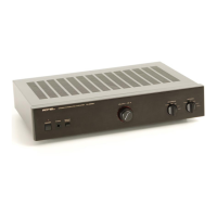
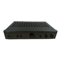
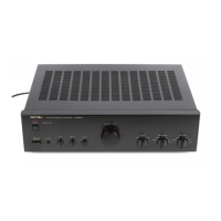
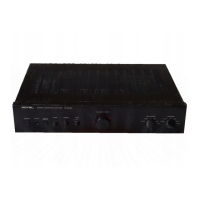
Provides physical dimensions and weight of the unit.

Parts List Overview

Capacitors, Fuses, and Connectors List

Lists part numbers for capacitors, fuses, and connectors.

Diodes and ICs List

Lists part numbers for diodes and integrated circuits.

Transistors and Resistors List

Lists part numbers for transistors and resistors.

Adjustment and Component Outlines

Bias Adjustment Procedure

Details the steps for bias adjustment using a voltmeter.

Component Case Outlines

Shows physical outlines of various components.

PCB Assembly Layout Diagrams

Main PCB Layouts

Illustrates the physical layout of various main PCB assemblies.

Schematic Diagrams - Amplifier Circuits

Main Amplifier Schematic (Part 1)

Presents the first part of the amplifier's schematic diagram.

Circuit Block Schematics

Details schematics for specific circuit blocks.

Schematic Diagrams - Power Supply and Control

Main Amplifier Schematic (Part 2)

Presents the second part of the main amplifier schematic diagram.

Power Supply Schematic

Details the schematic of the amplifier's power supply section.

Related product manuals