7 Technical data
Installation manual
11
RBLQ05+07C2V3
ROTEX HPSU monobloc compact outdoor unit
4P501825-1 – 2017.08
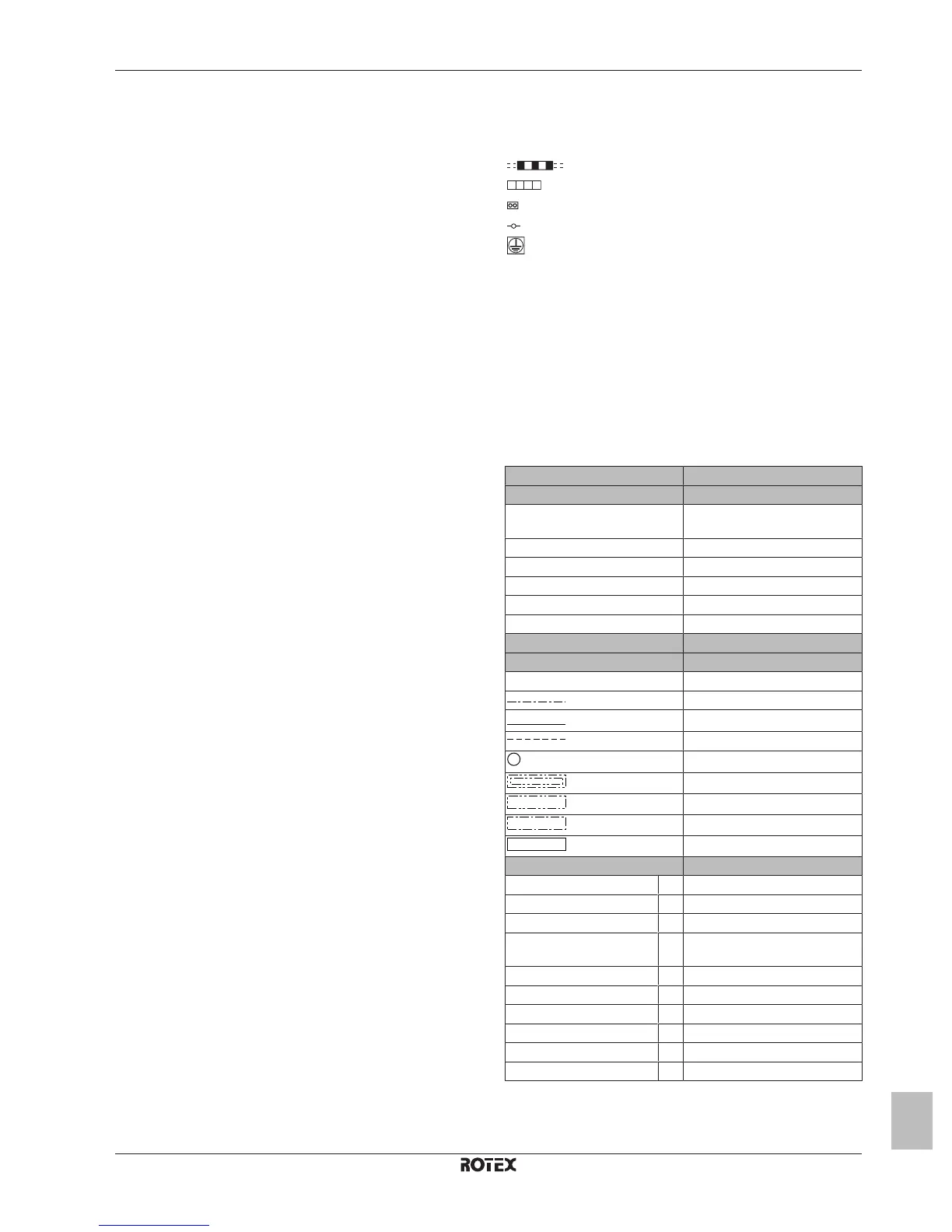
7.2 Wiring diagram: Outdoor unit
See the internal wiring diagram supplied with the unit (on the inside of the outdoor unit switch box cover). The abbreviations used are listed
below.
Outdoor unit: compressor module
C110~C112 Capacitor
DB1, DB2, DB401 Rectifier bridge
DC_N1, DC_N2 Connector
DC_P1, DC_P2 Connector
DCP1, DCP2, Connector
DCM1, DCM2 Connector
DP1, DP2 Connector
E1, E2 Connector
E1H Drain pan heater
FU1~FU5 Fuse
HL1, HL2, HL402 Connector
HN1, HN2, HN402 Connector
IPM1 Intelligent power module
L Live
LED 1~LED 4 Indication lamps
LED A, LED B Pilot lamp
M1C Compressor motor
M1F Fan motor
MR30, MR306,
MR307, MR4
Magnetic relay
MRM10, MRM20 Magnetic relay
MR30_A, MR30_B Connector
N Neutral
PCB1 Printed circuit board (main)
PCB2 Printed circuit board (inverter)
PCB3 Printed circuit board (service)
Q1DI Earth leakage circuit breaker
Q1L Overload protector
R1T Thermistor (discharge)
R2T Thermistor (heat exchanger)
R3T Thermistor (air)
S1NPH Pressure sensor
S1PH High pressure switch
S2~S503 Connector
SA1 Surge arrestor
SHEET METAL Terminal strip on fixed plate
SW1, SW3 Push buttons
SW2, SW5 DIP switches
U Connector
V Connector
V2, V3, V401 Varistor
W Connector
X11A, X12A Connector
X1M, X2M Terminal strip
Y1E Electronic expansion valve coil
Y1R Reversing solenoid valve coil
Z1C~Z4C Ferrite core
Field wiring
Terminal strip
Connector
Terminal
Protective earth
BLK Black
BLU Blue
BRN Brown
GRN Green
ORG Orange
PPL Purple
RED Red
WHT White
YLW Yellow
Outdoor unit: hydro module
English Translation
(1) Connection diagram (1) Connection diagram
External outdoor ambient sensor
option
External outdoor ambient sensor
option
Hydro switch box Hydro switch box
Indoor Indoor
NO valve Normal open valve
Outdoor Outdoor
Power supply Power supply
(2) Hydro switch box layout (2) Hydro switch box layout
(3) Notes (3) Notes
X4M Main terminal
Earth wiring
Wire number 15
Field supply
Several wiring possibilities
Option
Wiring depending on model
Switch box
PCB
(4) Legend (4) Legend
A1P Main PCB
A2P Current loop PCB
Q*DI # Earth leakage circuit breaker
R6T * External outdoor ambient sensor
option
TR1 Power supply transformer
X*M Terminal strip
X*Y Connector
PCB3 Service PCB
M2S # Shut-off valve
XAG1 Terminal strip
*: Optional
#: Field supply

 Loading...