3 x Installation
23
FA ROTEX Solaris RPS3 25M - 03/2010
Operation
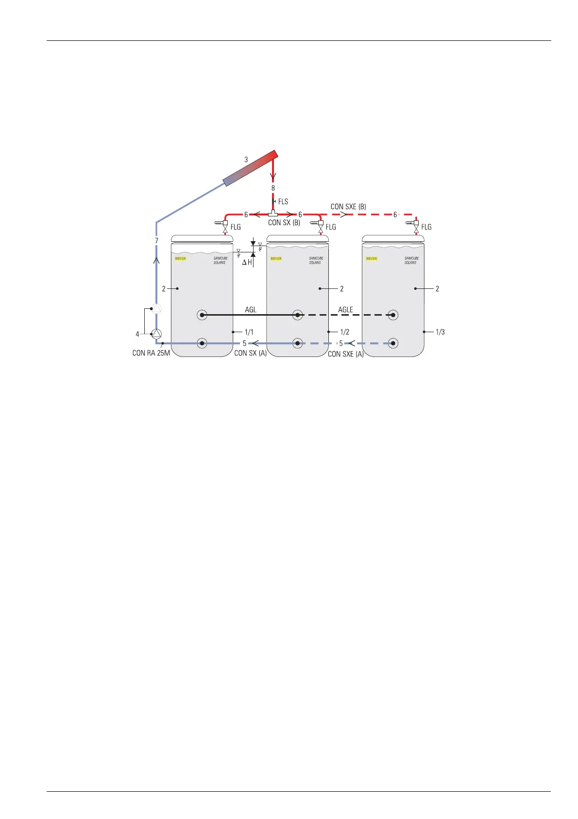
– The solar return is taken from the solar zone of one of the connected hot water storage tanks via the return connection pipe
(Image 3-32, Pos. 5).
– The common return is pumped to the collector array via the pump(s) (Image 3-32, Pos. 4) controlled by the Control unit RPS3
25M.
– The water is heated in the collector array and is fed as the solar flow into the DHW storage tank via the flow distributor pipe
(Image 3-32, Item 6 ).
1/1-3 Hot water storage tank
2 Non-pressurised area
3 Collector array
4 Circulation pump (bottom) and
optional booster pump (top)
5 Solaris return flow connection pipe (non-pressurised area)
6 Solaris flow manifold
7 Solaris return line
8 Solaris flow line
AGL Equalising pipe
AGLE Equalising pipe extension kit
CON RA 25M
connection set (return)
CON SX Storage tank extension kit
CON SXE Storage tank extension kit 2
CON ... (A) Return connection pipe from
storage tank extension kit
CON ... (B) Flow manifold from storage tank extension kit
FLS FlowSensor
FLG FlowGuard
∆H
Difference in level in non-pressurised storage tank area
Illustration 3-32 Operating principle of the common return flow pipe
 Loading...