CSD5 Servo Drive
P-4 Preface
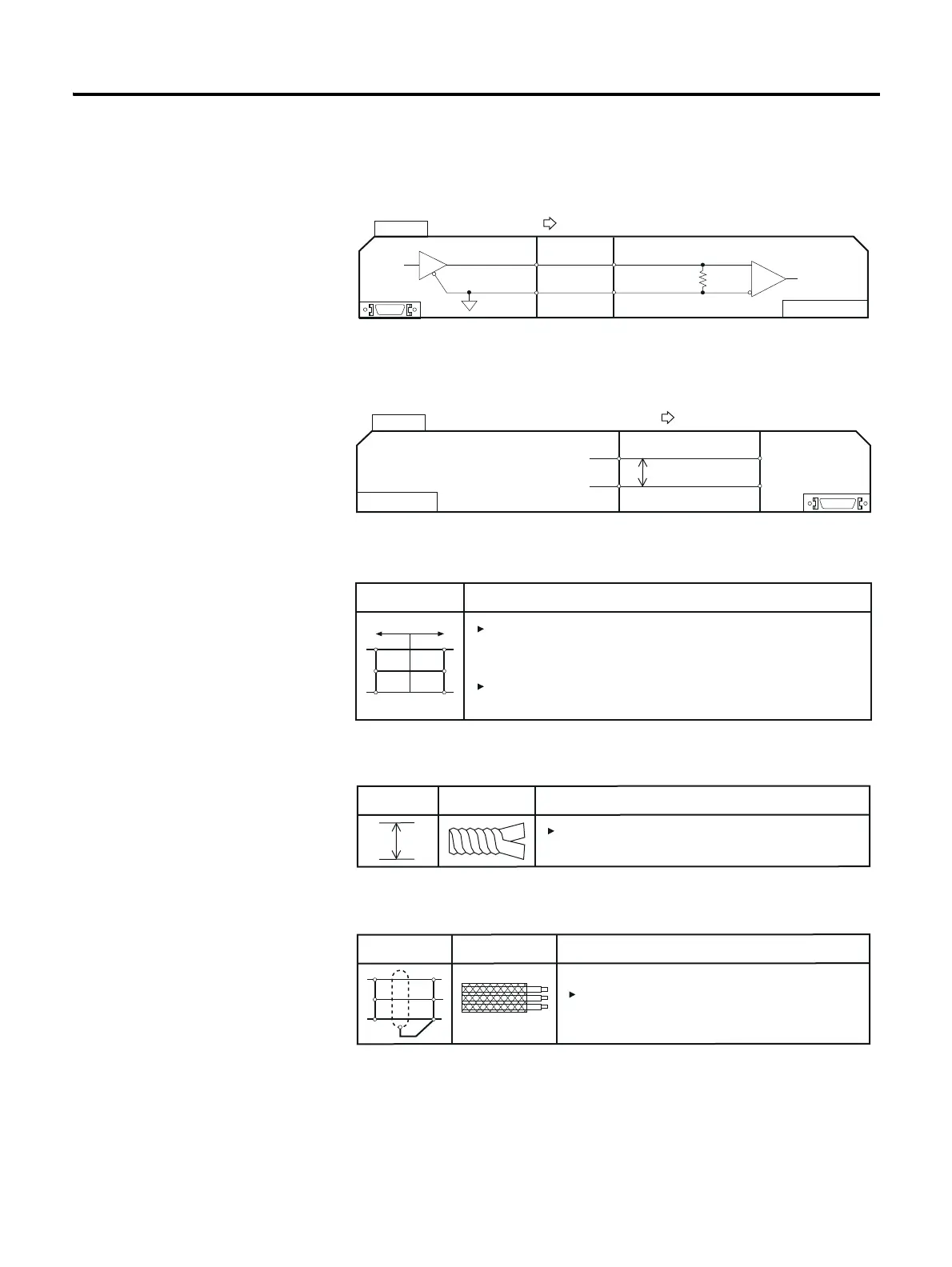
2. A figure box with both the top corners cut off diagonally represents a
circuit diagram. If I/O for I/O signal or a connector attached to the
servo driver is on the left, it is the output of I/O or servo drive.
3. If I/O for I/O signal or a connector attached to servo driver is on
the right, it is the input from the host controller to I/O or servo
drive.
4. The following shows the symbols used on the circuit
diagram.
5. The following figure shows a symbol used to show a twist pair wires
to prevent the noise generation.
6. The following figure shows a symbol used to show a shield pair wire
to prevent the noise generation.
Example
I/O
Output
R1
Host Controller
0[v]
Example
Speed Command
Host Controller
-10[v] ~ +10[v]
Input
P
VCMD+
VCMD-
19
20
I/O
Signal Description
The gure represents the pin number of the
connector, which can be marked with alphabets
tather than the numbers.
The contact is the connection between
the side A and B with the connector.
AB
1
2
3
1
2
3
Contact Point
Signal DescriptionFigure
P
The the wires where this symbol is located for
the noise prevention.
Signal DescriptionFigure
FG
Shield
Shield the wires where this symbol is located
for the noise prevention.



 To Next Page