264-1019-IM-V02
2
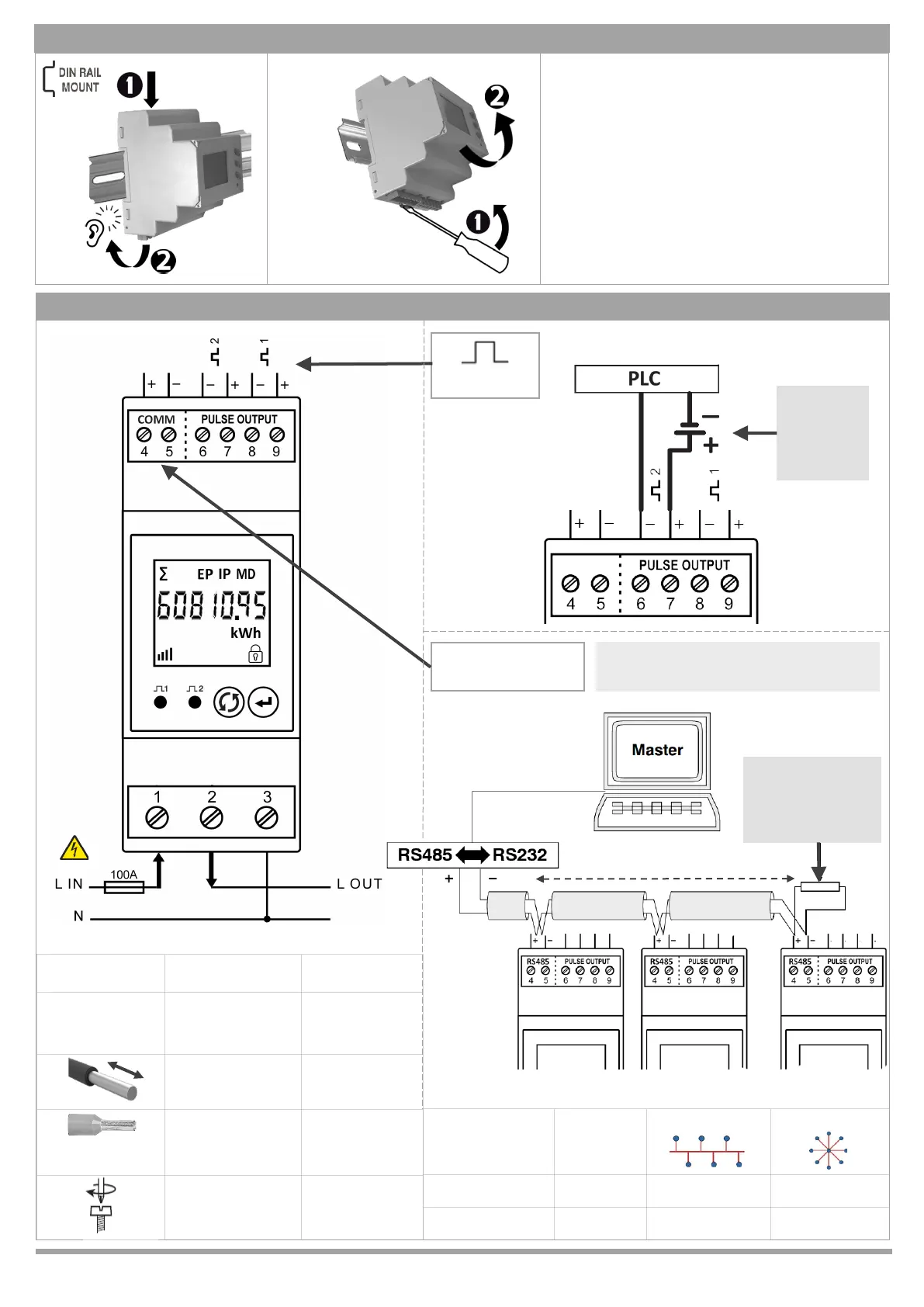
WIRING
Modbus
COMM Wiring
Topology
Daisy Chain Star Network
Terminals
4 | 5
Modbus
✓
+ | -
500m max, ≤ 32 devices*
Pulse Output
5...24V DC
PSU required
for ’Volt-free’
PLC or digital
input
DIN rail mounted, this device must be installed within
a suitable IP rated enclosure. Indoor use only.
The meter is intended to be installed in Mechanical
Environment ‘M1’, with Shock and Vibraons of low
signicance, as per 2014/32/EC Direcve.
The meter is intended to be installed in
Electromagnec Environment ‘E2’, as per
2014/32/EC Direcve.
Installaon Category III (300V L-N)
Protecon Class: II Polluon degree: II
MECHANICAL INSTALLATION
DISMOUNT
Typical Modbus conguraon shown
For MBus interface refer to Wiring Topology
Recommended
terminaon
resistor: 120Ω
(circuit length ≥ 50m)
* Booster required above max distance or devices
Terminals 1 / 2 / 3
4 > 9
Max Wire Size
2 AWG
35mm
2
Ø 6.5mm
13 AWG
2.5mm
2
Ø 2mm
12mm 7mm
Ferrule for
Stranded Cable
Ø 6mm max Ø 2mm max
0.9 Nm max 0.4 Nm max