4 5
10
20 30 400
Low
STO
MAX MAX
VA
KHzMINLOCK
Sh
V
NO.
SET
RCL
AC DC
MK HzmV AC FnF
%
TRMS
AUTO SendTEST
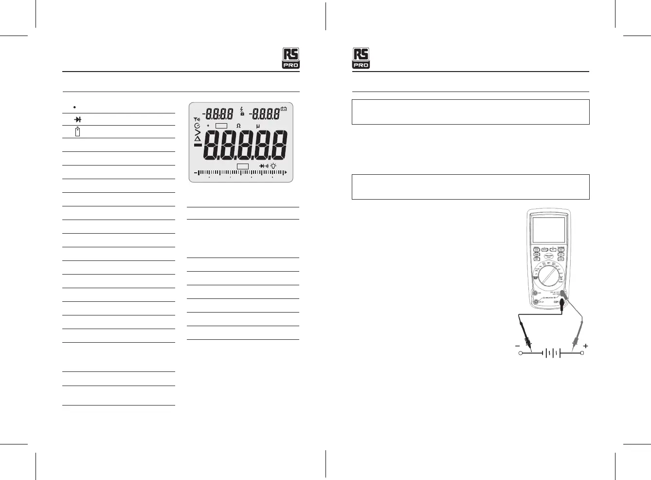
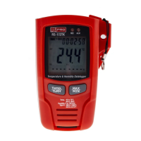
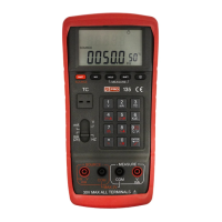
Symbols and Annunciators Operating Instructions
))) Continuity
Diode test
Battery status
n
nano (10
-9
) (capacitance)
μ
micro (10
-6
) (amps, cap)
m
milli (10
-3
) (volts, amps)
A
Amps
k
kilo (10
3
) (ohms)
F
Farads (capacitance)
M
mega (10
6
) (ohms)
Ω
Ohms
Hz
Hertz (frequency)
%
Percent (duty ratio)
AC
Alternating current
DC
Direct current
o
F
Degrees Fahrenheit
MAX
Maximum
NO
.
Serial number
S
Second
Left auxiliary display
Right auxiliary display
SET
Set up parameter
AC +DC
Alternating current + Direct
current
TRMS
Ture RMS
STO
Store
RCL
Recall
AUTO
Auto Range
Timing symbol
Backlight
Bargraph
PEAK
Peak Hold
V
Volts
REL
Relative
AUTO
Autoranging
HOLD
Display hold
o
C
Degrees Centigrade
MIN
Minimum
WARNING:
Risk of electrocution. High-voltage circuits, both AC and DC, are very
dangerous and should be measured with great care.
1.
ALWAYS
turn the function switch to the
OFF
position when the meter is not in use.
2. If “
OL
” appears in the display during a measurement, the value exceeds the range you
have selected. Change to a higher range.
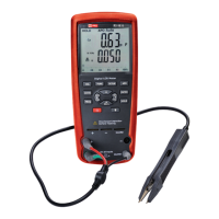
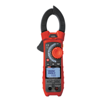
DC VOLTAGE MEASUREMENTS
CAUTION:
Do not measure DC voltages if a motor on the circuit is being switched
ON or OFF. Large voltage surges may occur that can damage the meter.
1. Set the function switch to the green
VDC
position.
2. Insert the black test lead banana plug into the
negative
COM
jack.
Insert the red test lead banana plug into the
positive
V
jack.
3. Touch the black test probe tip to the negative side
of the circuit.
Touch the red test probe tip to the positive side of
the circuit.
4. Read the voltage on the display.
Insulation Tester with Multimeter / EnglishInsulation Tester with Multimeter / English
25/01/2018 Version No. 00125/01/2018 Version No. 001