5
The operating temperature range indicated above excludes any heat generating
equipment operating within the unit. The presence on any such appliance will affect the
operational temperature characteristics.
3.5 To ensure adequate airflow for correct operation of the relative humidity control system the
incubator feet must be fitted to insert the adjustable feet, front pair first, tilt the incubator
backwards, screw the feet in to the required depth. Repeat the operation, tilting the incubator
forward for the rear pair.
3.6 Place the incubator in the working position. The unit is designed to be sited on a level surface
capable of bearing 32kg (approx – actual weight will depend on options fitted). It is
recommended that a spirit level be used on the centre of the middle shelf to position the
incubator, the feet can be individually adjusted to compensate for uneven surfaces. Fit the
anti-slip pads to the front feet. Purpose designed stands and stacking assemblies are also
available.
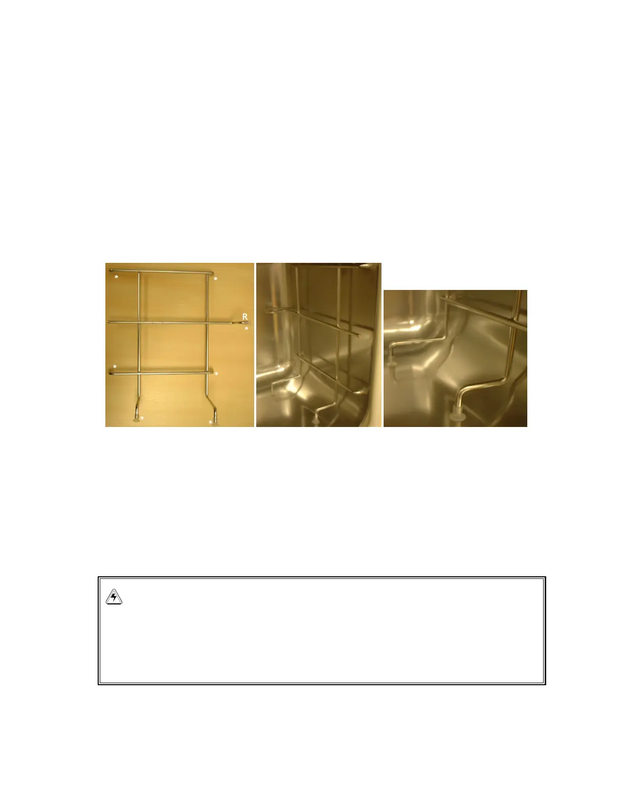
3.7 Assemble the shelf racks as follows:- Carefully remove any packaging. Fit 7 silicone rubber
suction cup feet to the shelf racks in positions indicated on the picture below left with an ‘*’.
Repeat for the opposite shelf rack.
To fit the shelf racks to the incubator:- The racks are ‘handed’ and the suction cup marked ‘R’
goes to the rear of the chamber as shown in the centre picture above. The suction cups will
adhere to the chamber walls dry, but can be dampened with distilled water to increase
adhesion if required. Ensure the shelf racks are fitted squarely to the chamber to enable the
shelves to sit on a level plane (picture above right).
3.8 Connect the CO
2
using the 6mm plastic tubing to the matching CO
2
inlet on the rear of the
incubator. Use the tubing clips provided to eliminate CO
2
leaks. Turn on the gas supply with
the pressure set to 0.35 BAR (5lbf/ in
2
). Remove the black protective cover from sensor
(keep for use when disinfecting). Ensure that the white porous sensor cover remains in place.
WARNING!
CO
2
levels.CO
2
is harmful in high concentrations. Any gases that may escape from the
unit have to be managed via adequate room ventilation or the use of an exhaust system.
Check compliance with the maximum permitted workplace concentration for CO
2
when
operating all units.