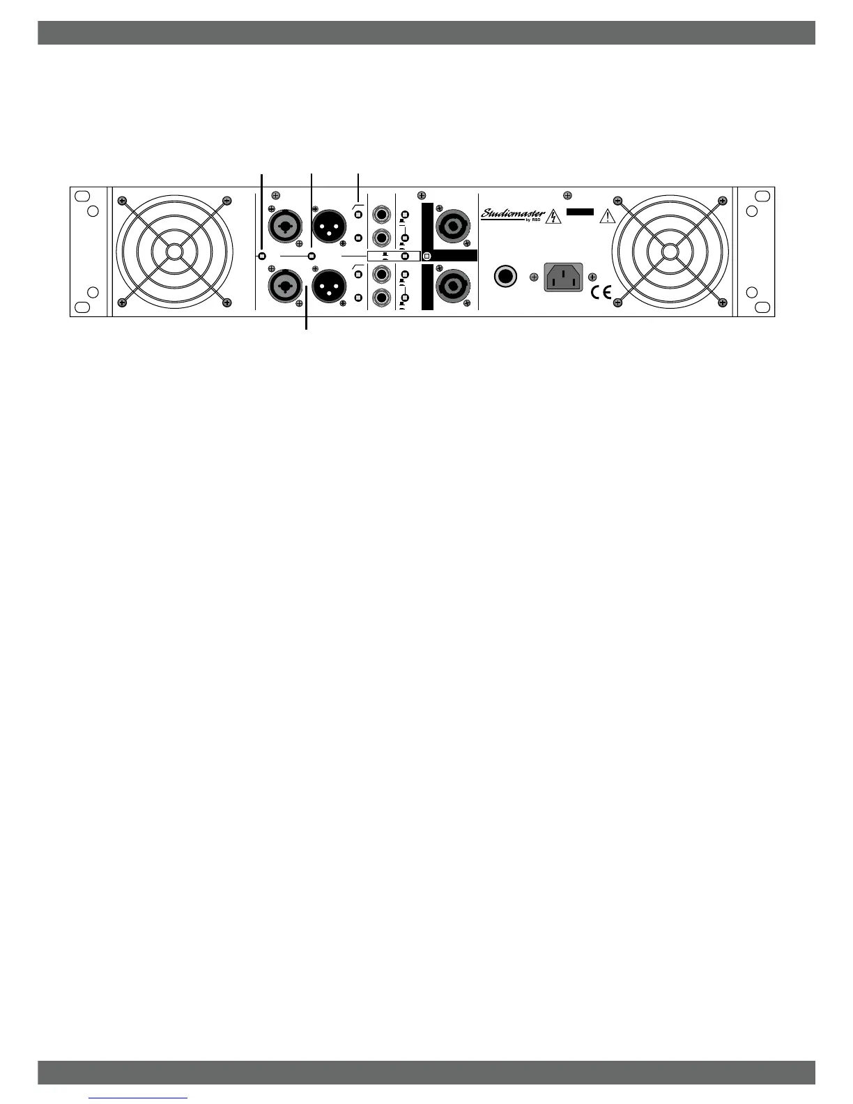
1. There are two INPUT CONNECTORS per channel. One is a combination 3
pin XLR and 3 pole (TRS) ¼" jack socket, the other a male XLR for linking to
other amplifiers. Both balanced and unbalanced signals can be used to drive
the amplifier.
XLR connector wiring
Balanced Operation Unbalanced operation
PIN 1 Ground PIN 1 Ground
PIN 2 +Ve/in-phase signal PIN 2 +Ve/in-phase signal
PIN 3 -Ve/out-phase signal PIN 3 Link to ground (pin1)
Jack connector wiring
Balanced Operation Unbalanced operation
3 pole/TRS/stereo ¼ " jack 2 pole/TS/mono ¼ " jack
TIP +Ve/in-phase signal TIP +Ve/in-phase signal
RING -Ve/out-phase signal SLEEVE Ground
SLEEVE Ground
2. Input GND LIFT (ground lift) switch removes the ground connection to all input
connectors. This can solve hum loop problems when connecting equipment
with different A.C. supplies.
Under no circumstances should the electrical safety ground (earth) from the
A.C. supply be disconnected.
3. PARALLEL INPUTS links Channel A input to Channel B. A single input signal
will now supply both channels. The volume levels of each channel can still be
adjusted individually.
4. 35Hz high pass filter reduces the level of very low frequency signals
reaching the speakers, improving bass clarity and power handling. It is
recommended that this filter is always used for live P.A/Sound re-inforcement.
Ported / Vented / 'bass reflex' speaker cabinets can be damaged if driven with
high power low frequency. For Studio monitoring where a totally flat response
is required, deselect the High Pass Filter. The filter has an 18dB / octave cut-
off slope.
Rear panel controls and features
STUDIOMASTER AX Amplifier Series
STUDIOMASTER AX Amplifier Series 3
1
2
3
4
230V
RISK OF ELECTRIC SHOCK
DO NOT OPEN
CAUTION
A
I
R
V
E
N
T
S
F
R
O
N
T
A
N
D
R
E
A
R
M
U
S
T
N
O
T
B
E
O
B
S
T
R
U
C
T
E
D
C
A
U
T
I
O
N
CIRCUIT
BREAKER
GND
LIFT
PARALLEL
INPUTS
INPUT B
LINK
B
CH
BRIDGE
CH. A
PIN 1+ =
PIN 2+ =
+
-