14
14
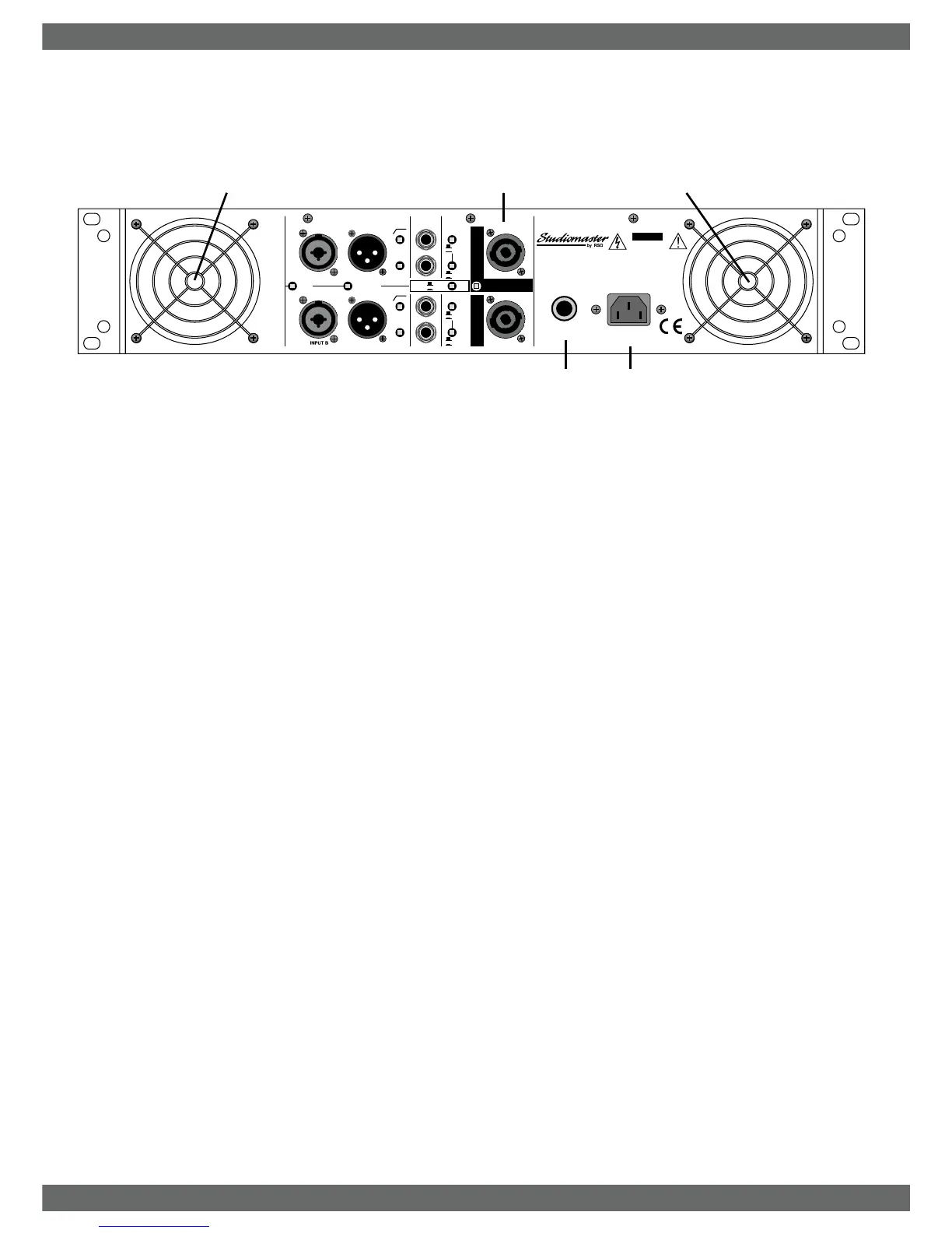
11. Speaker Wiring. Each channel uses SPEAKON NL4 connectors. Using cable
as specified (See CABLES) speaker connections are as follows:-
Each channel connected individually to a speaker:
PIN 1+ Positive (+) PIN 2+ Not used
PIN 1- Negative (-) PIN 2- Not used
Two Speakers connected to both channels in a single 4 core cable:
Use only Channel A connector wired:
Channel A PIN 1+Positive (+) Channel B PIN 2+ Positive (+)
Channel A PIN 1- Negative (-) Channel B PIN 2- Negative (-)
Bridged operation:
Use only Channel A connector wired:
PIN 1+ Positive (+) PIN 2+ Negative (-)
PIN 1- Not used PIN 2- Not used
Always ensure speaker cables are wired the same way. When any cable has
the pin wiring reversed, some speakers will be out of phase, usually resulting
in a loss of volume or bass.
12. Circuit Breaker will only activate if the amplifier has developed a fault or been
driven too hard into very low speaker impedances. The button on the circuit
breaker will protrude approximately 6mm when tripped. Check speaker wiring
and load before re-setting. To reset turn off the amplifier power switch and
push in the reset button. If the breaker trips again, the amplifier could have
developed a fault. If this happens refer to the Service Information section.
13. A.C. power inlet.
14. Fan ventilation holes. Do not obstruct.
Rear panel controls and features
STUDIOMASTER AX Amplifier Series
STUDIOMASTER AX Amplifier Series 5
11
230V
RISK OF ELECTRIC SHOCK
DO NOT OPEN
CAUTION
A
I
R
V
E
N
T
S
F
R
O
N
T
A
N
D
R
E
A
R
M
U
S
T
N
O
T
B
E
O
B
S
T
R
U
C
T
E
D
C
A
U
T
I
O
N
CIRCUIT
BREAKER
GND
LIFT
PARALLEL
INPUTS
INPUT B
LINK
B
CH
BRIDGE
CH. A
PIN 1+ =
PIN 2+ =
+
-
PIN 1+ =
PIN 1- =
+
-
ASSEMBLED IN CHINA
35Hz
LIMITER
OFF
HI
LO