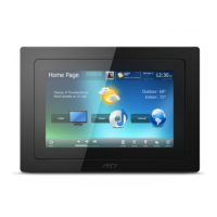
CONTROL INTERFACES, IST-10
3
www.rticontrol.com
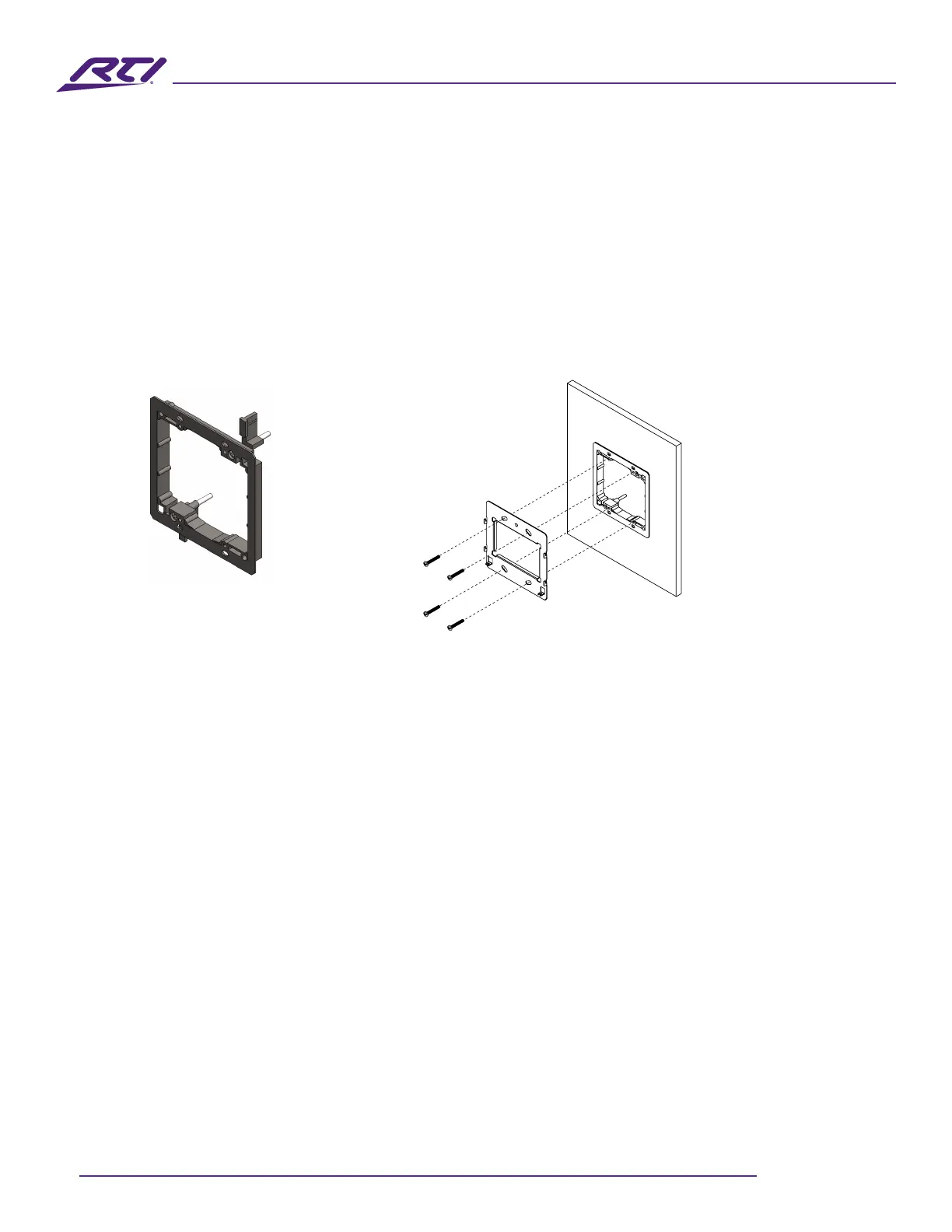
Landscape/Portrait Mounting
• Landscape orientation: Install the 2 gang low-voltage bracket on a wall in its normal position.
• Portrait orientation: Install the 2 gang low-voltage bracket on wall after rotating it 90 degrees in a
counterclockwise direction.
Install the IST-10 Mounting Bracket
• The IST-10 package includes a mounting bracket that MUST be used for installation.
• Use the included screws to mount the bracket onto a two gang low-voltage bracket.
• Verify that the bracket is level before tightening the captive screw on the IST-10.
2 Gang low voltage bracket
(Included)
IST-10 Mounting Bracket
(included)
Power the IST-10
The IST-10 is designed to be powered over an Ethernet connection with PoE or by connecting a 12VDC
power supply (not included), but not both.
PoE Connection
• PoE connection requires IEEE 802.3at standard. Utilize a network switch or PoE injector that meets this
standard.
• Connect the IST-10 using a standard T568A or T568B Ethernet cable from the network switch to the
LAN/PoE jack on the rear enclosure of the IST-10.
12VDC Power Supply
• You can provide power locally or remotely to IST-10 by utilizing a 12VDC/2A power supply (available
separately).
• If powering remotely, ensure the wire is of adequate gauge for the length of the run and the routing is
in compliance with local codes.
• Verify the polarity of the barrel connector on your power supply before connecting it to the IST-10. The
center pin of the IST-10 Power Connector is positive and the outer ring is negative.
• Plug the connector into the DC jack on the rear enclosure of the IST-10.