CONTROL INTERFACES, IST-10
Technical Support: support@rticontrol.com - Customer Service: custserv@rticontrol.com 4
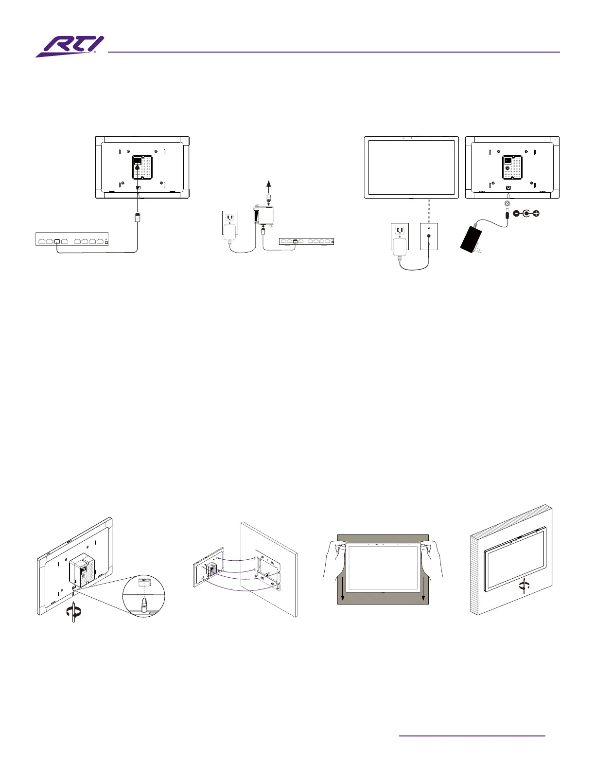
Power Up The IST-10
• The IST-10 will automatically power on when power is applied.
PoE Network Switch Cabling 12VDC Power Supply CablingPoE Injector Cabling
Network Switch
PoE Injector
PoE Network Switch
To IST-10
Line in wall
12VDC
2.1mm
Coaxial Plug
Network Switch
PoE Injector
To IST-10
Line in wall
12VDC
2.1mm
Coaxial Plug
Network Switch
PoE Injector
PoE Network Switch
To IST-10
Line in wall
12VDC
2.1mm
Coaxial Plug
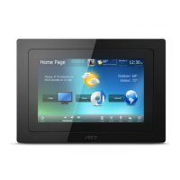
Install the IST-10
• Loosen the captive screw of the unit to the level indicated below in the diagram. Screw should not be
removed from the unit.
• Align the mounting frame hooks with the IST-10 mounting slots and gently pull the IST-10 unit down the
mounting bracket. Make sure the mounting hooks are properly engaged.
• To complete the installation, tighten the captive screw on the bottom part of unit, to secure the IST-10
on the mounting bracket.
• For Portrait orientation, rotate mounting bracket and IST-10 90 degrees in counterclockwise direction
before installation.
Tighten the captive
screw to secure
the IST-10 to the
mounting bracket.
Loosen captive
screw
Align mounting
frame hooks
Gently pull IST-10
down
Loosen
Tighten