EasyManua.ls Logo

Rugged Computing RRP660 - User Manual

Rugged Computing RRP660
5 pages
Print Icon
To Next Page IconTo Next Page
Loading...
1
I
nstallation instructions
for RRP660
ntercom and m
obile radios
Step #1: Location for intercom and radio
Find a good location to mount intercom and mobile radio. If possible mount mobile radio
no more than 3 feet from intercom. Standard mobile radio to intercom interface cables are
3 ft. long. Extensions are available when mounting requires more than 3 feet apart. PN#
CS-RADIO-EXT
Note: Be sure to mount away from ignition boxes to avoid RF interference.
Step #2 Mount intercom and radio
Mount intercom with L bracket mounts. Be sure to allow enough room behind the
intercom for the cables to be connected. The unique RRP600 mounting design allows you
to easily slide intercom out of the mounting brackets for plugging in cables and adjusting
radio transmit levels.
Mount mobile radio with the U bracket mounting supplied by manufacturer.
Step #3 Headset to intercom cables
Route the headset cables from the intercom to each seat. Be sure
to run cables in a location where there is not excessive heat or
they may get damaged. Always route cables away from ignition
boxes or coils as RF interference may occur. After routing
cables plug headset cables into the correct position into the
intercom. Be sure the driver cable is plugged into the driver
position on the intercom. If the co-driver and driver are reversed
the co-drivers mic will turn on when the driver pushes their
push to talk for car to car transmitting. Plug cables into back of
the intercom.
Question and Answer IconNeed help?

Do you have a question about the Rugged Computing RRP660 and is the answer not in the manual?

Summary

Intercom and Mobile Radio Location

Location for Intercom and Radio

Find a good location to mount intercom and mobile radio, keeping them close to minimize cable length.

RF Interference Avoidance

Mount components away from ignition boxes and coils to prevent radio frequency interference.

Intercom and Radio Mounting

Intercom Mounting

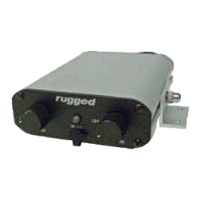
Mount the intercom using L brackets, ensuring space for cable connections.

Mobile Radio Mounting

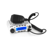
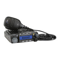
Mount the mobile radio using the manufacturer-supplied U bracket.

Headset Cable Installation

Headset Cable Routing

Route headset cables to each seat, avoiding heat and ignition sources for RF protection.

Driver;Co-driver Cable Connection

Ensure driver cable connects to the driver position to avoid mic activation issues.

Push-to-Talk (PTT) Installation

Hole Mount Push-to-Talk Installation

Drill a hole, mount PTT, connect adapter cable, and seal connections with shrink tube.

Velcro Mount Push-to-Talk Installation

Mount PTT with Velcro, ensure cable clearance for steering wheel lock-to-lock.

Push-to-Talk Cable Safety

Locate PTT cables away from pinching or binding areas to prevent damage.

Intercom to Radio Cable Connection

Intercom to Radio Cable Connection

Connect the 5-pin connector to the intercom and the serial connector to the radio.

External Speaker Port Connection

Connect the 3.5mm plug to the radio's external speaker port.

Cable Compatibility Note

Note that cables may vary depending on the specific radio brand and model.

Antenna and Coax Cable Installation

Antenna Mounting Location

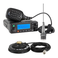
Mount the antenna in the center of a metal roof or roll bar for best performance.

Coax Cable Routing

Route coax cable away from ignition sources to avoid interference and RF issues.

Coax Cable Length Handling

Do not coil excess coax cable; route it around the car to prevent transmit problems.

Power Connections

Radio Power Connection

Connect the car-to-car radio power cable directly to the battery, do not remove fuses.

Intercom Power Connection

Connect the intercom power cable directly to the battery, do not remove fuses.

Direct Battery Powering

Always connect power cables directly to the battery to avoid ground loop issues.

Intercom Operation and Setup

Initial Intercom Setup

Turn on intercom by rotating volume clockwise, set VOX fully clockwise initially.

VOX Intercom Sidetone Test

Test VOX by speaking into the mic and listening for your voice in the headset.

Squelch Adjustment

Adjust squelch counter-clockwise until mics turn off, then speak to activate.

Car-to-Car Radio Operation

Radio Channel Selection and Volume

Select radio channel and adjust incoming volume using radio's controls.

Transmit Activation

Use push-to-talk buttons; intercom LED turns orange, car radio LED turns red.

Transmit Level Adjustment

Radio Gain Control

Adjust RADIO GAIN on intercom to fine-tune transmit volume and background noise.

Music Input

Music Device Connection

Plug music devices into the 3.5mm front port or rear Molex for audio input.

Music Volume Control

Music volume is controlled solely by the connected music device.

Final Installation Check

Cable Management and Security

Ensure all cables are secured away from heat/damage and all hardware is tight.

Optional Accessory Cable and DSP

Accessory Cable Hookup

Connect accessory cable to the AUX post for cell phones, cameras, or stereos.

Cell Phone Hookup and Volume

Connect cell phone, adjust transmit level via back panel volume pot.

Optional DSP Upgrade

DSP upgrade removes background noise for clearer communication.

Conclusion and Support

System Conclusion

The RRP600 intercom is highly adjustable and configurable for various applications.

Customer Support Contact

Contact Customer Service and Tech Line for questions or concerns.

Rugged Computing RRP660 Specifications

General IconGeneral
BrandRugged Computing
ModelRRP660
CategoryRadio
LanguageEnglish

Related product manuals