63
17-04-2003
01
15-01-2004
DATE
COMPILER TECO/ATI
REG. CODE
1-5302-467
MODEL N°
50707
DATE OF ISSUE
REVISION
ENDORSED
XI
128
129
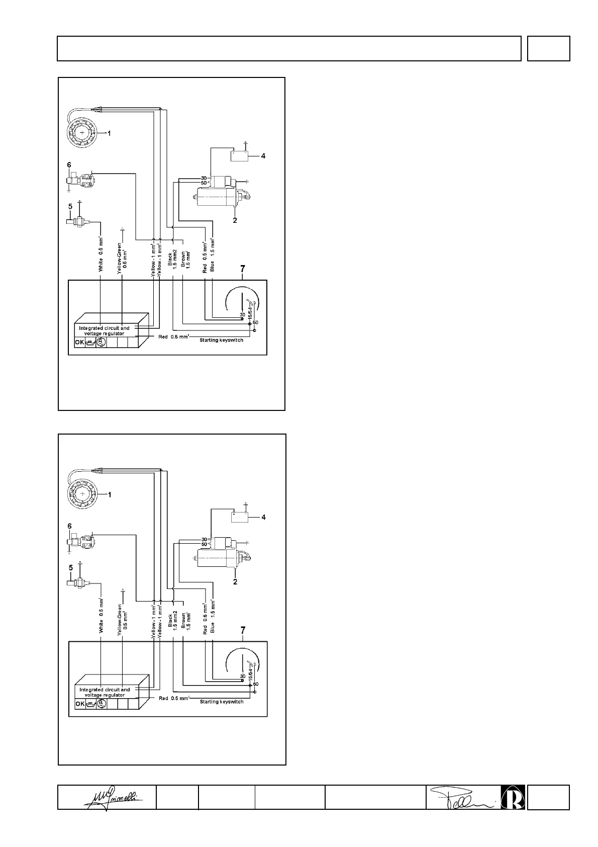
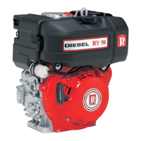
ELECTRICAL SYSTEM
12V electric starter diagram with voltage regulator built into the
ignition panel
Components:
1 Alternator
2 Starter motor
4 Battery
5 Pressure switch
6 Solenoid valve
7 Ignition switch
Note: The battery, which is not supplied by RUGGERINI, should
have 12V nominal voltage rating and a capacity of not less
than 44 Ah / 210 Amp. of fast discharge intensity.
12V electric ignition layout with motor protection (optional)
Components:
1 Alternator
2 Starter motor
4 Battery
5 Pressure switch
6 Solenoid valve
7 Ignition switch
8 Panel
Note: The battery, which is not supplied by RUGGERINI, should
have 12V nominal voltage rating and a capacity of not less
than 44 Ah / 210 Amp. of fast discharge intensity.