The product will automatically identify a device with a supported fast charging mode. At this
time the device supports the QC2.0 、 QC3.0 、 APPLE 2.4A/2.1A/ 1A/0.5A 、 Android DCP 、
SAMSUNG.
(
Note
:
This quick charge agreement recognition model is for reference only, because cell phone
upgraded quickly, it can't be absolutely accurate identification
)
Press ‘NEXT’ to switch to the Charging Recording Interface.
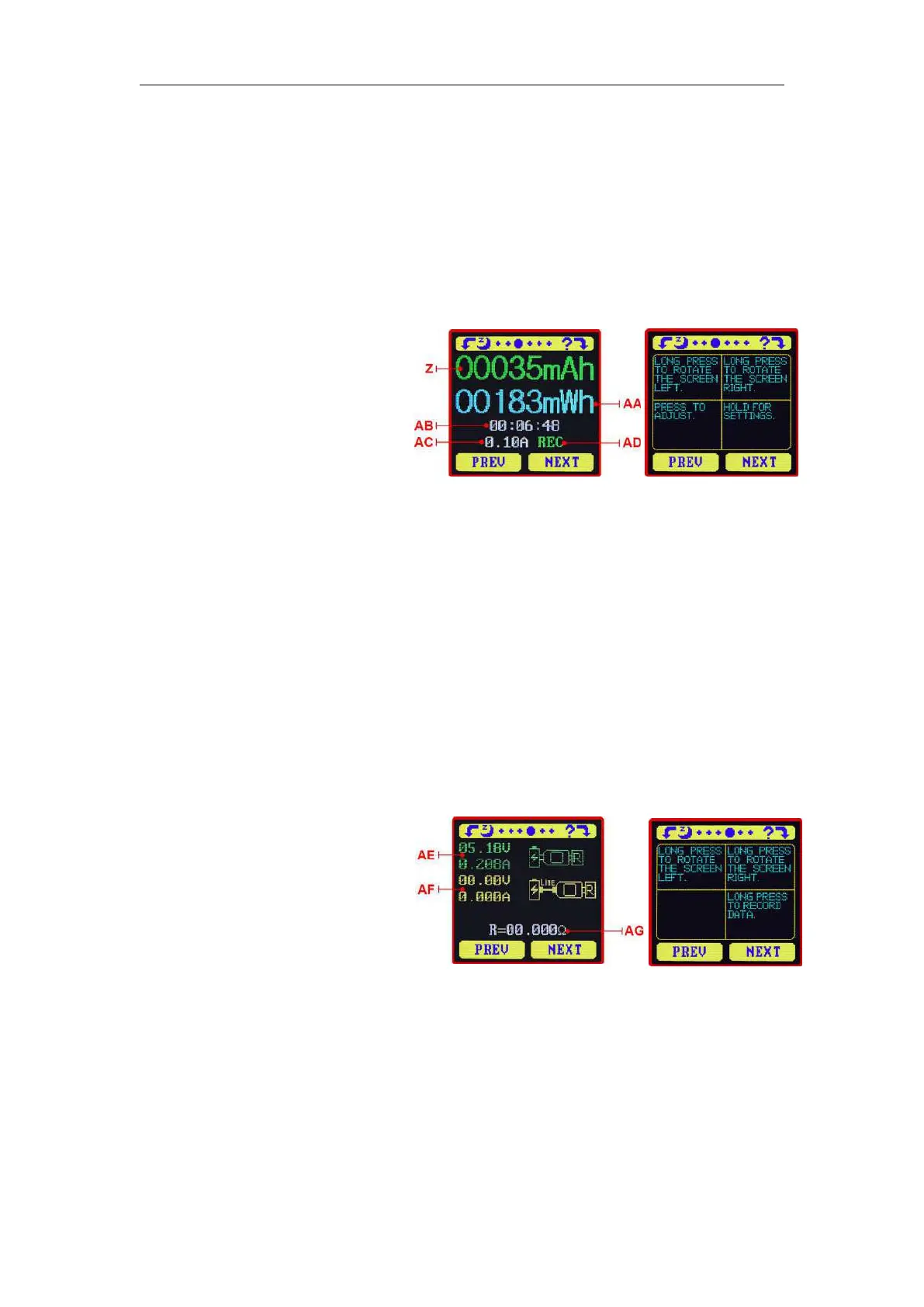
1.6.3 Interface 3: Charging Recording Interface
Z:Accumulated Capacity
AA: Accumulated Energy
AB:Time display:The total accumulated
recording time.
AC : Capacity/Energy statistics trigger
current
AD:REC:recording status indicator.
‘REC’ displayed in red indicates that
recording is stopped. ‘REC’ displayed in green indicates that recording is in progress.
After power on, when the current flowing is greater than the Low Current trigger value. The
system automatically begins to record the accumulated capacity, energy, and time elapsed. The
‘REC’ indicator will change from red to green.
To set the Current trigger value, press and hold the "Next" button to highlight the value then
press the ‘PREV’ button to adjust the value as required. The value can be set anywhere between
0.01A- and 0.30A. (10mA to 300mA).
Press "Next" button to switch to the Data Connection Cable impedance Measurement Interface.
1.6.4 Interface 4: Data Connection Cable Impedance Measurement
Interface.
AE
:
USB Tester directly connected to
the power supply with Voltage and
Current values displayed
AF
:
USB Tester connected via a data
connection cable with Voltage and
Current values displayed.
AG
:
Data Connection Cable resistance.
Measurement procedure:
First, connect the USB Tester directly to the power supply and adjust the appropriate load
current (recommended value 1A) . Press and hold the ‘NEXT’ button to begin recording data. The
indicator prompt will stop flashing .
Second, unplug the USB Tester and then reconnect it to the power supply via the Micro
USB/Type-C IN data connection cable and adjust the load current to the same value as in the first
step. Press and hold the ‘NEXT’ button to begin recording data. The indicator prompt stops
flashing and the Data Connection Cable resistance measurement test is completed and the value