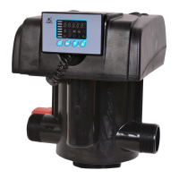
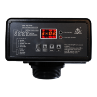
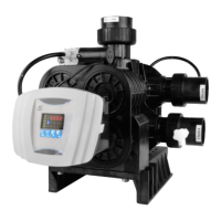
MODEL F71B/F71G/F67C/F67G/N75A/N75B
11
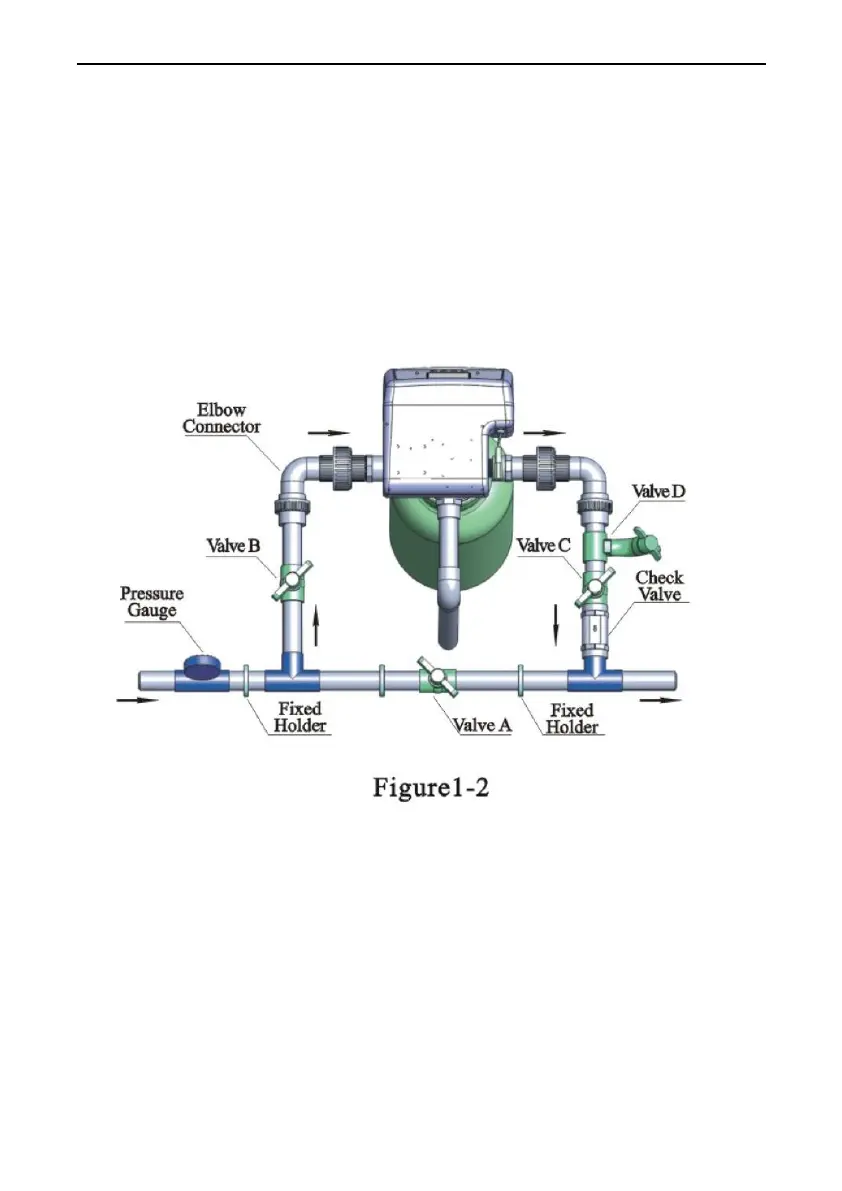
② Pipeline connection
a. As figure 1-2 shows, install a pressure gauge in water inlet.
b. Install valve A, valve B, valve C and valve D in the inlet and outlet
pipeline. The valve D is sampling valve.
c. Install the check valve in the outlet pipeline.
d. Inlet pipeline should be in parallel with outlet pipeline. Support inlet
and outlet pipeline with fixed holder.
Note:
●If making a soldered copper installation, do all sweat soldering before
connecting pipes to the valve. Torch heat will damage plastic parts.
●When turning threaded pipe fittings onto plastic fitting, use care not to
cross thread or broken valve.