EasyManua.ls Logo

Runxin N75A1 - System Config and Flow Rate Curves

Default Icon
53 pages
Print Icon
To Next Page IconTo Next Page
To Previous Page IconTo Previous Page
Loading...
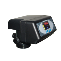
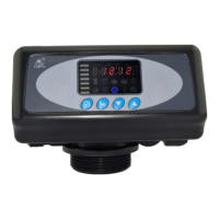
MODEL F71B/F71G/F67C/F67G/N75A/N75B
26
3.3. System Configuration and Flow Rate Curve
A. Product Configuration
Product configuration with tank, filter materials volume
Tank Size
Volume
of Filter
Material
Carbon Filter
Sand Filter
Filtering
Flow
Rate
Backwas
h Flow
Rate
Filtering
Flow
Rate
Backwas
h Flow
Rate
mm
L
m3/h
m3/h
m3/h
m3/h
φ180×1130
16
0.3
0.9
0.6
1.3
φ205×1300
25
0.4
1.1
0.8
1.7
φ255×1390
40
0.6
1.7
1.2
2.6
φ300×1390
60
0.8
2.5
1.7
3.8
φ355×1670
100
1.2
3.4
2.4
5.2
φ400×1670
120
1.5
4.5
3.1
6.8
φ450×1670
150
2
5.9
4.1
8.8
φ500×1800
200
2.4
7
4.9
10.6
φ600×1800
300
3.4
10
7
15.2
Attention: the filtering flow rate of carbon filter is calculated based on the
12m/h operation rate; the backwash flow rate is calculated based on the
10L/(m
2
*s) backwash intensity; the filtering flow rate of sand filter is
calculated based on the 25m/h operation rate; the backwash flow rate is
calculated based on the 15L/(m
2
*s) backwash intensity.

Related product manuals