EasyManua.ls Logo

Rx Clear HydroSalt - User Manual

Rx Clear HydroSalt
24 pages
Print Icon
To Next Page IconTo Next Page
Loading...
Electronic Chlorine Generator
Installation & Operation Manual
Millstream Distribution LLC
1-800-253-4775
www.millstreamdstr.com
Question and Answer IconNeed help?

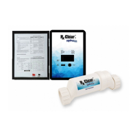
Do you have a question about the Rx Clear HydroSalt and is the answer not in the manual?

Summary

IMPORTANT SAFETY INSTRUCTIONS

READ AND FOLLOW ALL INSTRUCTIONS

Key instructions for safe operation and installation of the equipment.

OPERATION

IDEAL CHEMICAL LEVELS

SALT LEVEL

How to Add or Remove Salt

CONTROLS

Maintaining the Rx Clear HydroSalt Chlorine Generator

Mild Acid Washing

Winterizing

INSTALLATION

Plumbing

Flow switch

Electrolytic Cell

Wiring

TROUBLESHOOTING

Diagnostic Displays

Information accessed via the diagnostic button on the LCD display.

Common Problems and Solutions

Troubleshooting guide for common issues and their resolutions.

Overview

The Rx Clear HydroSalt is an automatic chlorine generation system designed for pool and spa sanitation. It operates by converting a low concentration of salt (sodium chloride) in the pool water into free chlorine through electrolysis, effectively killing bacteria and algae. The system is designed to handle purification needs for residential swimming pools up to 40,000 gallons (150,000 liters).

Important Safety Instructions:

  • Always disconnect AC power during installation.
  • Do not permit children to use this product.
  • A green colored screw inside the wiring compartment must be connected to the grounding means in the electric supply service panel with a continuous copper wire equivalent in size to the circuit conductors supplying the equipment.
  • One bonding lug (two for Canadian models) is provided on the external surface for connecting the local common bonding grid in the area of the swimming pool, spa, or hot tub with an insulated or bare copper conductor not smaller than 8 AWG US/6 AWG Canada.
  • All field-installed metal components within 10 feet (3 meters) of the pool, spa, or hot tub (e.g., rails, ladders, drains) must be bonded to the equipment grounding bus with copper conductors not smaller than 8 AWG US/6 AWG Canada.
  • Consult state and county codes and local NEC codes before installation.

Key Technical Specifications:

  • Salt Level: Ideal range is 3,000-4,000 ppm (parts per million), with 3,400 ppm being optimal. The system will shut down if salt levels are excessively high or operate inefficiently if too low.
  • Free Chlorine: 1.0 to 3.0 ppm.
  • pH: 7.2 to 7.6.
  • Cyanuric Acid (Stabilizer): 50 to 100 ppm.
  • Total Alkalinity: 80 to 120 ppm.
  • Calcium Hardness: 200 to 400 ppm.
  • Metals: 0 ppm.
  • Saturation Index (Si): -0.2 to 0.2. The Si is calculated as: Si = pH + Ti + Ci + Ai - 12.1 (where Ti, Ci, and Ai are determined from charts based on temperature, calcium hardness, and total alkalinity, respectively).
  • Power Input: 120/240 VAC.
  • Fuse: 20 amp mini ATO fuse on the circuit board.
  • Chlorine Generation Temperature: Will not produce chlorine below 50°F.

Usage Features:

  • Main Switch:
    • AUTO: Normal operation, produces chlorine according to the "Desired Level %" setting during the filtering/pumping cycle.
    • SUPER CHLORINATE: Electronically "super chlorinates" (shocks) the water for 24 hours (filter pump must be on) or until power is turned off. Used for high bather load, heavy rainfall, or cloudy water.
    • OFF: Prevents the electrolytic cell from energizing, stopping chlorine generation. (Note: For servicing, turn off power at the circuit breaker, not the OFF switch).
  • Desired Level Adjustment Knob: Controls the amount of chlorine generated, ranging from 5% to 100% output capacity.
  • Salt Display: Shows current salt concentration in ppm (parts per million) or grams per liter (g/L). Can also display pool water temperature in Fahrenheit or Celsius.
  • Indicator LEDs:
    • POWER: Illuminates when the system has input power.
    • GENERATING: Steady when in normal operation; flashing indicates a need to check pool water.
    • SUPER CHLORINATE: Illuminates during super chlorination.
    • REMOTE: Indicates control by a remote system (not available).
    • NO FLOW: Illuminates when the flow switch detects no flow, stopping chlorine generation. Flashing indicates flow is restored, with a 60-second delay before generation restarts.
    • CHECK SALT: Flashing indicates low salt level (below 2500 ppm) and low efficiency. Steady illumination means salt level is too low, and the system has shut down.
    • HIGH SALT: Illuminates when salt level is too high, and the system has shut down. Requires dilution of pool water.
    • CHECK CELL: Flashing indicates reduced cell efficiency or scheduled inspection. Steady illumination means greatly reduced cell efficiency, and the system has stopped producing chlorine.
  • Diagnostic Button: Sequential pushes display pool temperature, cell voltage, cell current, desired output percentage, instant salinity, product name, software revision level, cell type, salt calibration, and end of loop.

Maintenance Features:

  • Water Chemistry: Maintain proper pH, alkaline content, calcium levels, salt, and stabilizer. Professional testing is recommended at least twice per season.
  • Adding Salt:
    • In-ground pools: Add directly into the shallow end with the filter pump on.
    • Above-ground pools with main drains: Add directly in front of the return jet. Run filter pump for 24 hours with suction from the main drain (or pool vacuum).
    • Above-ground pools without main drains: Add directly into the pool and brush to speed dissolution.
    • Crucial: Do NOT add salt directly to skimmers or the main drain, as this can shorten cell life due to high salt concentration and reduced flow.
  • Lowering Salt Concentration: Only by partially draining the pool and refilling with fresh water.
  • Cell Inspection: Remove and visually inspect the cell every 3 months (or when "Check Cell" LED flashes after approximately 500 hours of operation). Press the diagnostic button for 3 seconds to reset the timer after inspection/cleaning.
  • Cell Cleaning:
    • Use a high-pressure garden hose to flush off scale.
    • If unsuccessful, use a plastic or wood tool to scrape deposits.
    • WARNING: DO NOT USE A METAL SCRAPER, as this will scratch and damage the plates.
    • Mild Acid Washing (for severe cases): Turn off power, remove cell. Mix a 4:1 solution of water to muriatic acid in a clean plastic container (ALWAYS POUR ACID INTO WATER, NEVER WATER INTO ACID). Wear protective glasses, clothing, and chemical-resistant gloves. Soak the cell for FIVE minutes (ensuring the wire harness compartment is NOT submerged), then rinse with a high-pressure garden hose. Repeat if necessary.
  • Winterizing: Drain all water from the electrolytic cell, flow detection switch, pump, filter, and supply/return lines in areas with freezing temperatures. The electronic control can withstand winter weather.
  • Spring Start-up: DO NOT turn on the system until pool water chemistry is balanced. Add metal remover and polymer-based (non-copper) algaecide at the beginning of each season.

Installation:

  • Mounting: The control is in a rain-tight enclosure, suitable for outdoor vertical mounting on a flat surface. Mount a minimum of 5 ft. (2 meters) horizontal distance from the pool/spa, with knockouts facing downward. Do not block the four sides of the control or mount in a panel/tightly enclosed space.
  • Plumbing: Install the cell and flow switch in the return line to the pool, after all other pool equipment (filter, heater, solar, etc.). Ensure 12” of straight pipe run before the flow switch. Verify the arrow on the flow switch points in the direction of water flow.
  • Wiring: Turn off power at the circuit breaker. Wire to the LOAD SIDE of the filter pump timer so it only powers on when the pump is running. Refer to the wiring label and diagrams. The unit is shipped with a 220V configuration; jumpers must be installed for the desired voltage before turning on.
  • Bonding: Bond the system to the pool bonding system with an 8 AWG copper wire (6 AWG Canada) using the lug on the bottom of the enclosure.
  • Electrolytic Cell and Flow Switch Cables: Connectors plug into the HydroSalt™; the flow switch uses a telephone jack-like connector on the bottom of the enclosure.

Rx Clear HydroSalt Specifications

General IconGeneral
BrandRx Clear
ModelHydroSalt
CategoryWater Filtration Systems
LanguageEnglish

Related product manuals