8
■ Scabbard
■ Combination wrench (5/8 in. X 3/4 in.)
■ 230 ml bar and chain lubricant
■ Bottle of 2-stroke lubricant
■ Shoulder strap hanger (with mounting hardware)
■ Shoulder strap
■ “J” handle assembly (with mounting hardware)
■ Hanger cap
■ Operator’s manual
WARNING
If any parts are damaged or missing do not operate this
product until the parts are replaced. Failure to heed this
warning could result in serious personal injury.
WARNING
Do not attempt to modify this product or create
accessories not recommended for use with this product.
Any such alteration or modication is misuse and could
result in a hazardous condition leading to possible
serious personal injury.
WARNING
To prevent accidental starting that could cause serious
personal injury, always disconnect the engine spark
plug wire from the spark plug when assembling parts.
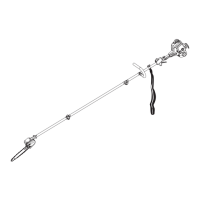
ATTACHING THE “J” HANDLE
See gure 2.
■ Place the bottom J-handle clamp on the drive shaft as
shown. Insert the tab on the top J-handle clamp into
the slot on the bottom J-handle clamp.
■ Insert the end of the J-handle between the clamps
so that holes align and handle will be located to the
operator’s left.
■ Push the bolt through the clamp and handle.
■ Install flat washer and lock nut to hold the assembly
in place.
■ Adjust the position of the handle to the area indicated
by the label on the drive shaft housing.
■ Tighten the nut securely.
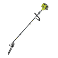
INSTALLING THE SHOULDER STRAP, HANGER AND
ATTACHMENT
See gures 2 - 4.
When operating this unit, you must wear a shoulder strap
to support the unit.
To install the shoulder strap hanger:
■ Remove the lock nut, flat washer, and bolt from the
shoulder strap hanger.
■ Pull apart the ends of the hanger to expand slightly.
Position the hanger along the shaft to a location providing
optimum balance and control of the tool.
NOTE: Make sure that the hanger does not cover the
WARNING label on the shaft.
■ Squeeze hanger ends together to retighten.
■ Reinstall the bolt, flat washer, and locking nut to
secure.
■ Connect the latch on the shoulder harness to the strap
hanger.
The pruner attachment connects to the power head, or for
extra reach to an extension shaft, by means of a coupler
device.
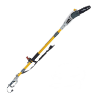
To install the pruner attachment:
■ Loosen the knob on the coupler of the power head and
remove the end cap from the pruner attachment.
■ Push in the button located on the shaft of the pruner
attachment. Align the button with the guide recess on
the power head shaft coupler and slide the two shafts
together. Rotate pruner attachment shaft until button
locks into the positioning hole.
NOTE: The attachment should only be operated with
the blade in a vertical position.
■ Tighten the knob securely.
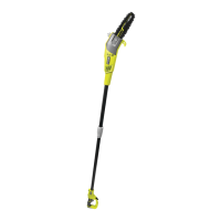
■ Repeat previous steps to attach extension shaft to
power head.
NOTE: If the button does not release completely in
the positioning hole, the shaft is not locked into place.
Slightly rotate from side to side until the button is
locked into place.
WARNING
Be certain the knob is fully tightened and button is
locked into place in positioning hole before operating
equipment. Check it periodically for tightness during
use to avoid serious injury.