ASSEMBLY
11
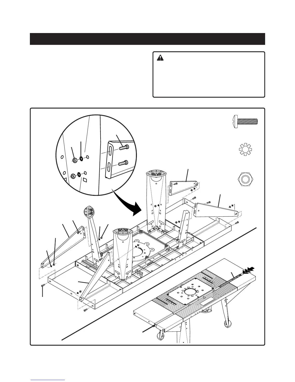
TO ATTACH THE LEG SUPPORTS
See Figure 4
6. Attach each pair of leg supports (E) and (F) to
extension and table legs. Place each support as shown
below and fasten together using 12 pan head screws
(AD), 12 toothed washers (AM) and 12 hex nuts (AP)
provided. Use a #2 Phillips screwdriver to keep from
stripping the screw heads.
7. Place the router table on its legs.
CAUTION:
Control the alignment of tabletop and the two
extenions by sliding miter bar (K) through miter guide
slot as shown below . If necessary loosen scews and
adjust alignment of tabletop and extensions.
Retighten screws (AD) as described in figure 2 on
side 10.
AD (12)
AM (12)
AP (12)
Fig. 4
AP
AM
AD
AM
AP
AD
F
E
E
F
K
MITER GUIDE SLOT
AP
AM
AD