ASSEMBLY
12
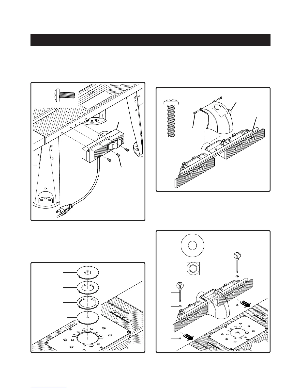
Fig. 5
TO ATTACH THE SWITCH BOX
See Figure 5
8. Use a #2 Phillips screwdriver to attach switch box (H) to
the table with 3 self tapping screws (AC).
AC (3)
H
AC
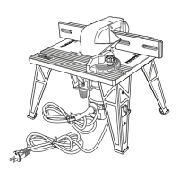
Fig. 6
X
Y
Z
W
ASSEMBLE THE INSERTS
See Figure 6
9. Three of the inserts are for use with a specific size bit.
Insert (W) is for used for mounting the router by using
the centering pin (description later in your manual).
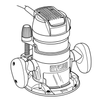
TO ATTACH THE FENCE
See Figure 7
10. Attach the safety shield (A) to the fence (B) with 2 pan
head screws (AE). Use a #3 Phillips screwdriver to
tighten the screws.
Fig. 7
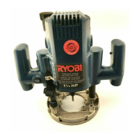
Fig. 8
See Figure 8
11. Place the 2 washers (AK) on top of the 2 holes in the
fence, insert the 2 knob screws (L) into the holes and
fasten on the other side with the 2 square nuts (AR).
NOTE: Do not tighten the 2 square nuts at this stage.
AK (2)
AR (2)
AE (2)
B
A
AE
L
AK
AR