Preliminary manual AN 401 Plus V2 r12 25/10/12
2.11 Connection to external Inputs
On AN 401 plus are available four opto-insulated inputs. Their behaviour depends from the
selected instrument’s operating mode. Please refer to the chosen operating mode.
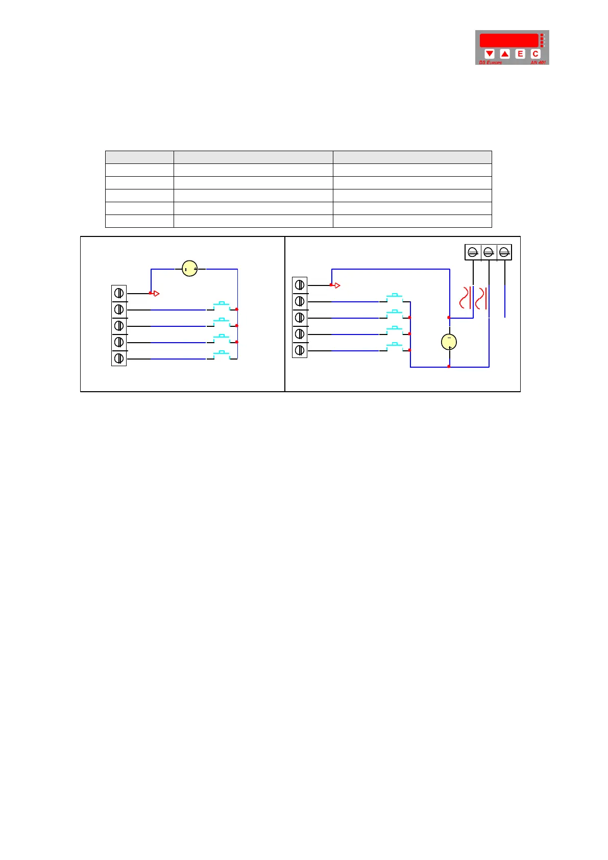
Digital inputs can be connected to the “INPUT” screw terminal.
Maximum voltage: +28 Volt
Maximum voltage: +28 Volt
Maximum voltage: +28 Volt
Maximum voltage: +28 Volt
Fig. 1a: Insulated connection Fig.1b: NOT insulated connection
On over mentioned figures (Fig.1a and Fig.1b) are shown connections to be used for
pushbuttons but it is possible to connect: relay, TTL lines, transistors, etc.
In order to light-on the LED emitters, internal to the opto-couplers, a voltage ranging from +12
to +28 Vdc must be supplied to each input.
Opto-coupler’s electrical characteristics:
Insulation: 200 V peak
Settling time: from 18 µS to 10 mSec
Release time: from 18 µS to 10 mSec
2.12 Earth connection (CE norms)
In order to obtain the maximum immunity to electrical disturbs, following are some
recommendations:
Power supply common must be connected to earth.
If AN401 plus is powered by a power supply separated from the rest of the machine,
connect the “EARTH” screw terminal to the nearest earth connection (avoid earth loops
or earth connections disturbed by high power devices).
When connecting signal lines from AN401 plus (analogue outputs, RS232 serial lines,
etc) please remember that they are referred to earth, in order to avoid the creation of
earth loops
Best condition is obtained when all commons (signal and power supply) are connected
to earth at the same point (star connection).
Avoid wiring any input/output cable, directed to AN 401, with high power cables.
If the application is free from electrical disturbs, Earth connection may be avoided.
1
2
3
4
5
INPUT
EXGND
KEY1
+24Vdc
1
2
3
1
2
3
4
5
INPUT
EXGND
+24Vdc
KEY2
KEY3
KEY4
KEY1
KEY2
KEY3
KEY4
EARTH
 Loading...