Preliminary manual AN 401 Plus V2 r12 25/10/12
For longer connections, between transducer and instrument, verify that at
the transducer’s end You can measure a power supply voltage of 18 Vdc minimum.
To calibrate an AN401plus, connected with a PCX_ss magnetostrictive transducer, follow the
general procedures described in the “AN401plus quick start manual” or in chapter 5 of this manual.
Calibration or measurement displaying is as for load cells, pressure transducers or other standard
transducers.
2.7 Connection of 0 to 5 Volt [O1 option] and 0-10 Volt [O2 option] output cards
2.8 Connection of 4-20 mA [O3 option] and 0-20 mA [O4 option] output cards
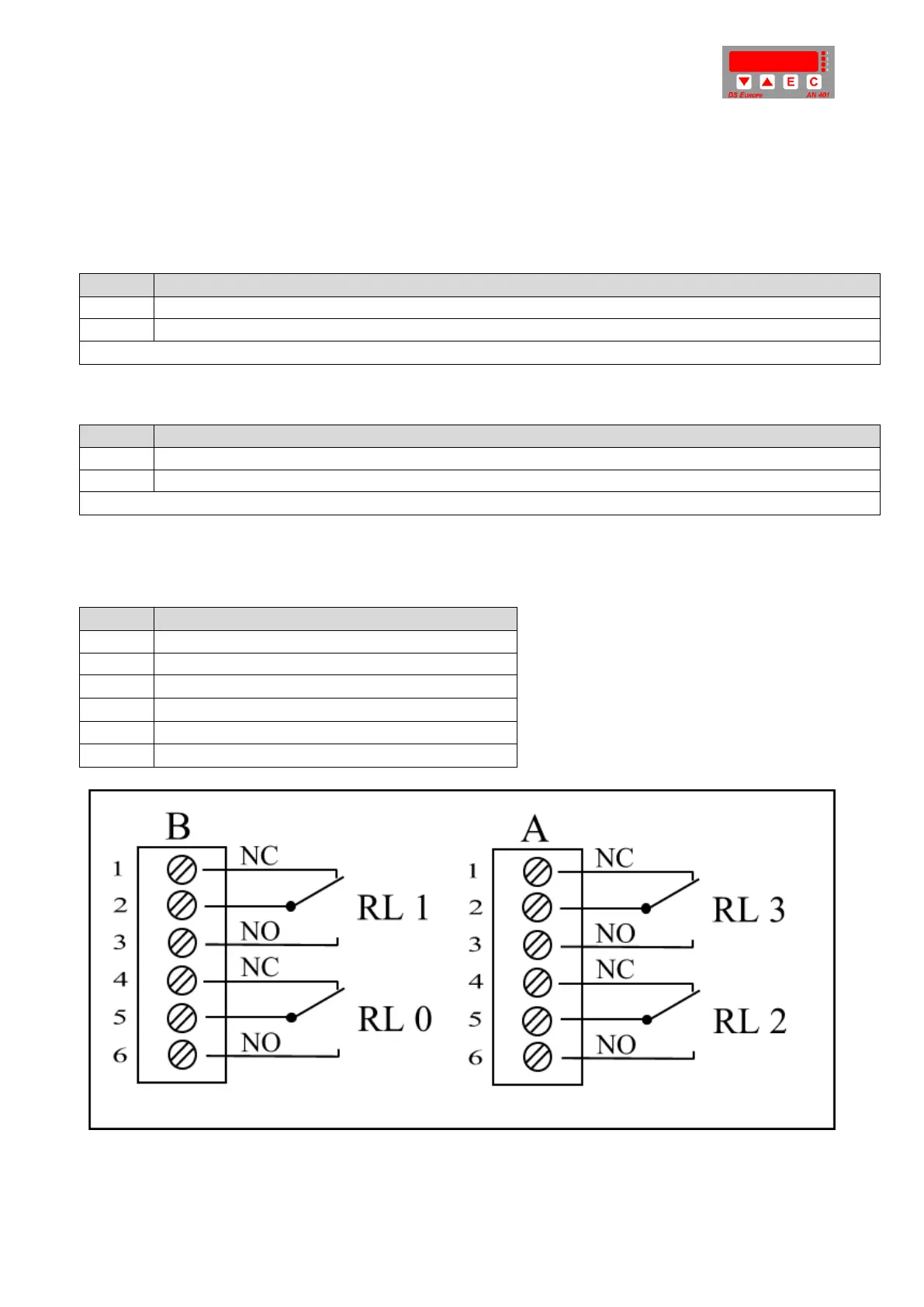
2.9 Connection of I/O card [D0 option]
Relays electrical characteristics:
Maximum voltage: 30 Vdc
Maximum current: 2 A
Maximum power: 1W
Operate time: from 2 to 15
mS .
Fig. 10: Connection of relay board.
Voltage analog output: 0 to 5 Volts (O1 option board) or 0 to 10 Volts (O2 option board).
AGND common for 0 to 5 V or 0 to 10 V analog output signal.
Terminals 2-4-5-6 not connected.
3 Wires Current analog output: 4 to 20 mA (O3) or 0 to 20 mA (O4).
AGND common for Current analog output: 4 to 20 mA (O3) or 0 to 20 mA (O4).
Terminals 1-4-5-6 not connected.
Relay 1 Normally Closed contact
Relay 1 Normally Open contact.
Relay 2 Normally Closed contact.
Relay 2 Normally Open contact.
 Loading...