SAFT
COMPONENT MAINTENANCE MANUAL
1606-l
C.
Detailed description (Refer to pages 1001-O and 1001-l)
2.
- Maximum instantaneous power:
at +23'C (+73'F): 12 V and 15 s 8.85 kW
at -18'C (+O"F): 12 V and 15 s 4.80 kW.
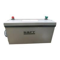
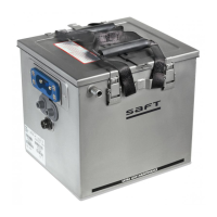
The battery has 20 VP 160KM (320A) cells in a stainless steel box.
The box (040A) has a lining of thin sheets of insulation and of
spacers (190A)
The cover (060A) has one insulator (070A) and 2 protectors (080A).
The cells are held in place by a hold-down bar (240A).
This hold-down bar is mounted inside box and fixed by 2 screws (1lOA)
and 2 nuts (120A).
The rigid links (290A thru 310A). made of nickel-plated copper,
connect the cells together.
Two insulated holes through the cover (060A) for the battery
terminals (250A).
These terminals (250A) connect the battery to the aircraft.
The battery has a removable cover (060A). It is fixed by 2 screws
(020A) with 2 spring washers (030A).
Operation
A. Charge
(1) Flight charge
Adjust the recharger to make sure the battery is correctly
charged in flight. Do a recharger check as frequently as
possible.
At the usual temperature of +20°C (+68"F), the constant charge
voltage must be 28.5 volts. If the climatic or battery operating
conditions cause the cell temperature to increase to +4O"C
(+104"F), adjust the recharger to 27.5 to 28 volts. This is to
prevent a fast loss of the electrolyte reserve and a shorter
life for the cells.
For a given voltage adjustment, the higher the battery
temperature, the higher the remaining charge current.
The consumption of water from the electrolyte is directly in
proportion to the remaining charge current. Thus it is necessary
to accurately know the usual operating temperature of the
batteries to permit the batteries to be charged in the best
conditions.
24-39-06
Page 2
Apr 01192
The document reference is online, please check the correspondence between the online documentation and the printed version.