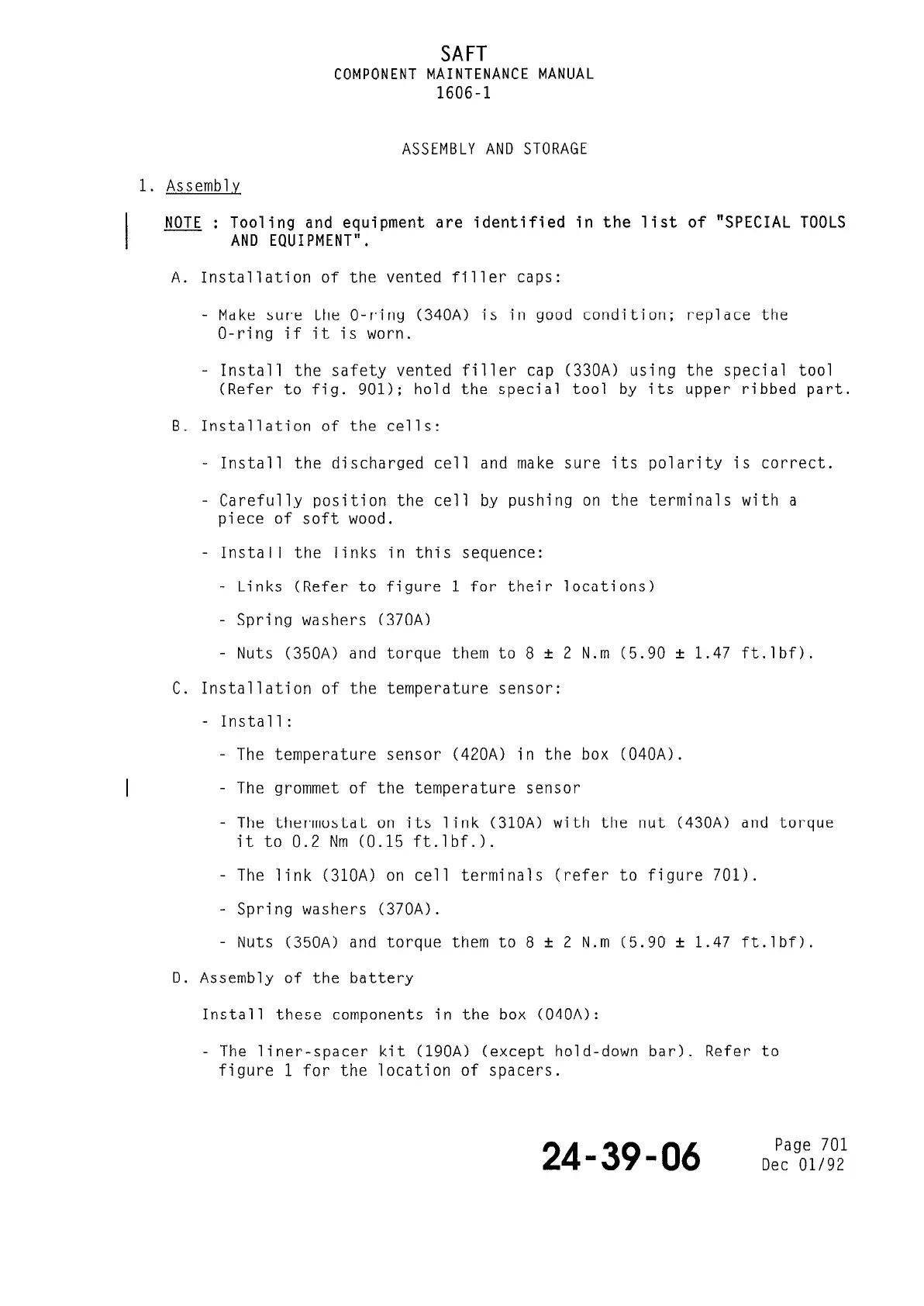
SAFT
COMPONENT MAINTENANCE MANUAL
1606-l
ASSEMBLY AND STORAGE
1. Assemb1.y
I
: NOTE
Tooling and equipment are identified in the list of "SPECIAL TOOLS
AND EQUIPMENT".
A. Installation of the vented filler caps:
- Make sure the O-ring (340A) is in good condition: replace the
O-ring if it is worn.
- Install the safety vented fil
ler cap (330A) using the special tool
(Refer to fig. 901); hold the
special tool by its upper ribbed part.
B. Installation of the cells:
- Install the discharged cell and make sure its polarity is correct.
- Carefully position the cell by pushing on the terminals with a
piece of soft wood.
- Install the links in this sequence:
- Links (Refer to figure 1 for their locations)
- Spring washers (370A)
- Nuts (350A) and torque them to 8 + 2 N.m (5.90 + 1.47 ft.lbf).
C. Installation of the temperature sensor:
- Install:
- The temperature sensor (420A) in the box (040A).
- The grommet of the temperature sensor
- The thermostat on its link (310A) with the nut (430A) and torque
it to 0.2 Nm (0.15 ft.lbf.1.
- The link (310A) on cell terminals (refer to figure 701).
- Spring washers (370A).
- Nuts (350A) and torque them to 8 + 2 N.m (5.90 f 1.47 ft.lbf).
D. Assembly of the battery
Install these components in the box (040A):
- The liner-spacer kit (190A) (except hold-down bar). Refer to
figure 1 for the location of spacers.
24-39-06
Page 701
Dee 01/92
The document reference is online, please check the correspondence between the online documentation and the printed version.