2 CIRCUIT DESCRIPTION RT2047 DSC - PART II
9641
PAGE 2-3
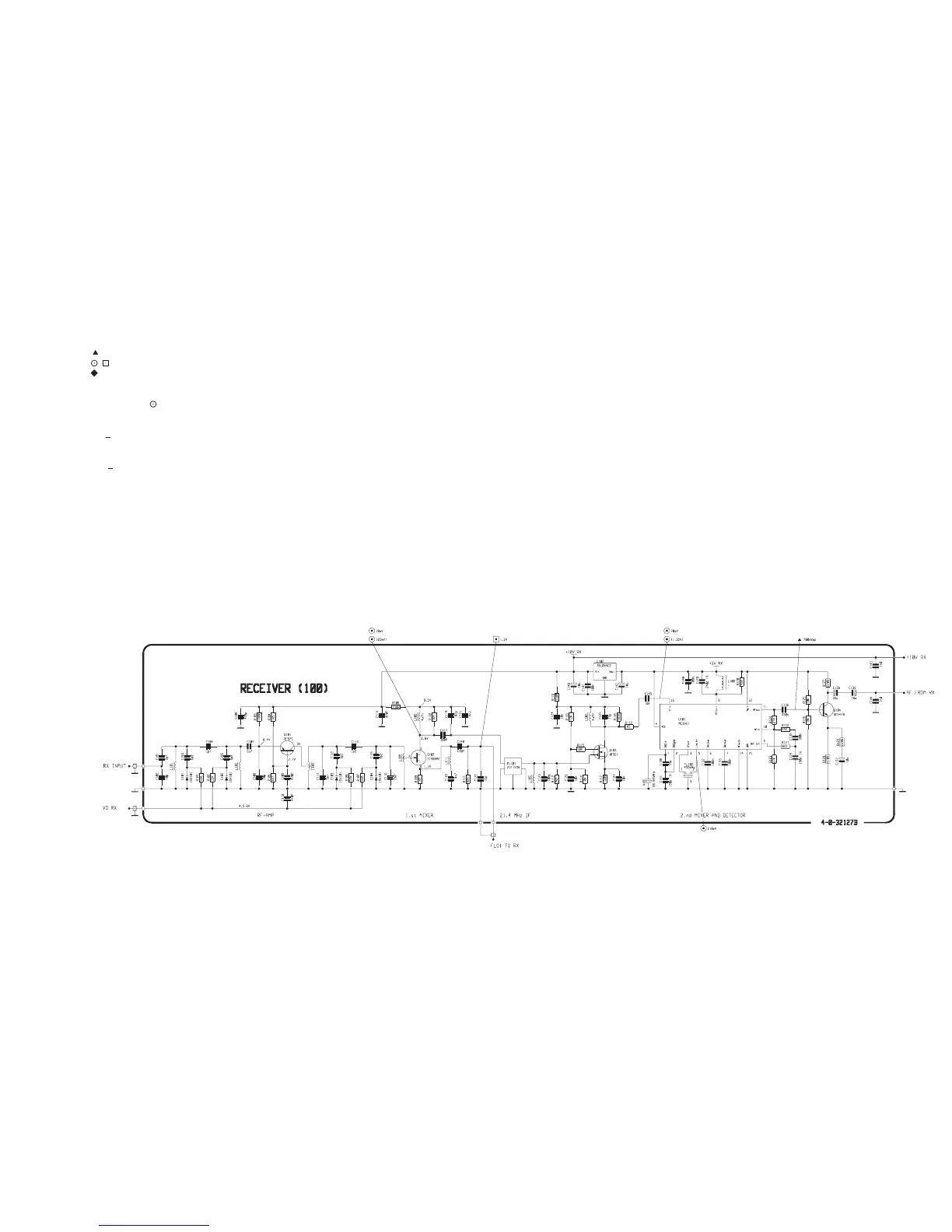
DIAGRAM RECEIVER UNIT MODULE 100
AC voltages outside frame of diagram.
: Measured with oscilloscope or frq. counter.
: Measured with test probe.
: Connections to module.
[ ] : Approx. measurement with test probe.
Test conditions:
Voltages without brackets:
Antenna signal 1 mV pd:
Df= +3 kHz; f
m
= 1 kHz
Voltages in brackets:
Antenna signal 10 mV pd:
Df = + 3 kHz; f
m
= 1 kHz
This diagram is valid for PCB rev. 32127B.