2 CIRCUIT DESCRIPTION RT2047 DSC - PART II
PAGE 2-28
9543
2.8 DUPLEX FILTER MODULE 800
With a duplex filter, DF801, placed in the station it is possible to operate in full duplex mode with only one
antenna installed.
The duplex filter consists of 7 cavities, three in the Rx-section and four in the Tx-section.
The cavities in the Tx-section are stagger tuned. Two cavities (D-E) are suppressing the noise in the
receiving band 160.625 MHz - 162.025 MHz with Minimal insertion loss in the transmission band.
The function of the other two cavities (F-G) is to provide a band stop filter within the image frequency band
range of the duplex distance, 4.6 MHz: 151.425 MHz -152.825 MHz.
The cavities (A-B-C) in the Rx-section are stagger tuned. They are suppressing the transmitting
frequencies with Mid. insertion loss in the receiving band.
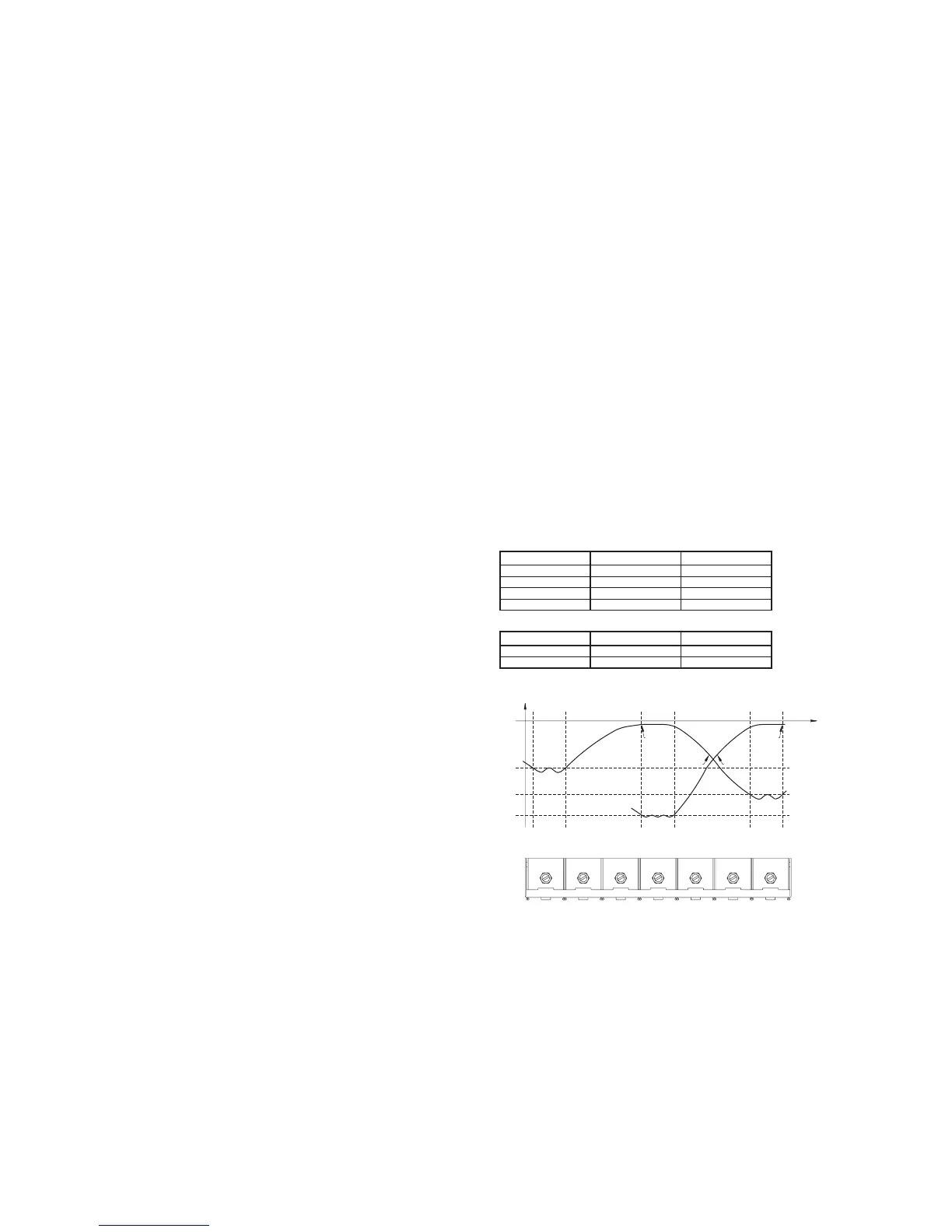
See the plot of duplex filters frequency response below.
NB: The duplex filter is adjusted with special measuring equipment and should be adjusted by S.P. Radio
A/S only.
TECHNICAL DATA FOR DUPLEX FILTER FOR VHF RT146 - RT2047.
75$160,77(5 G% 5$1*(0+]
Band-stop attenuation -30 151.425 - 152.825
Band-stop attenuation -47 156.025 - 157.425
Insertion loss. Max 1.6 -
Return loss. Mid 1.7 -