2 CIRCUIT DESCRIPTION RT2047 DSC - PART II
2.15.3 ADJUSTMENT PROCEDURE
ADJUSTMENT OF OUTPUT VOLTAGE.
Measure the output voltage across C126 with a load equal to the consumption of a VHF unit in receive
condition (0.5 - 0.8A). Adjust R105 until the output is 13.2V if necessary.
ADJUSTMENT OF MAX. CURRENT.
Check that the output voltage is still 13.2V with a load of 5.8A (2.3 ohm) across the output.
Change the load to 1,5 ohm by connecting 4.3 ohm in parallel with the 2.3 ohm. The voltage will then be
10.5V and the output 7A. If necessary adjust the output to 10.5V with R111.
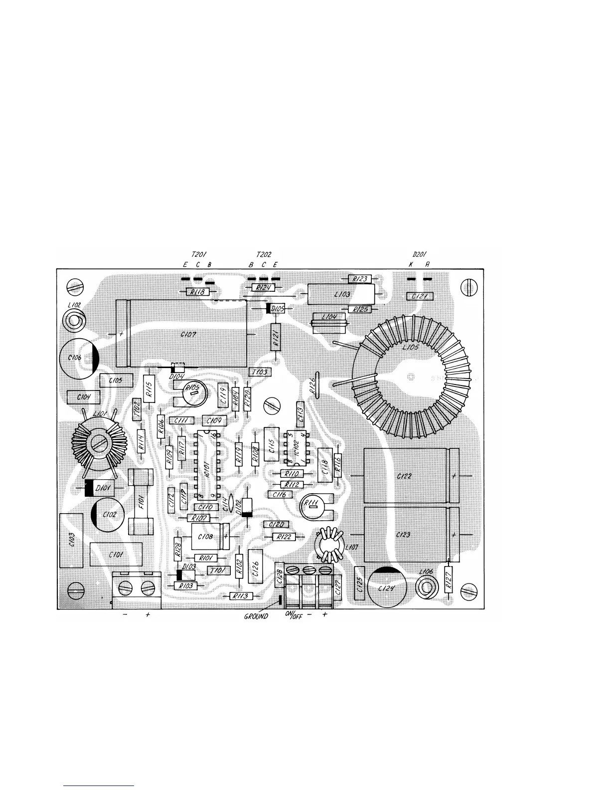
COMPONENT LOCATION DC POWER SUPPLY N418
View from component side with lower side tracks.
23818C
PAGE 2-40
9543