Do you have a question about the Sailor RT4722 and is the answer not in the manual?
Company background and market leadership in maritime radio communication.
Recognition of SAILOR products as reliable and technologically superior maritime radio equipment.
Details on SAILOR GMDSS solutions, COMPACT 2000, and System 4000.
Importance of deck officer training for GMDSS and available software training programs.
Global certified service network ensuring professional and uniform service for GMDSS equipment.
Manufacturer responsibility for reliable supply of GMDSS equipment and spares.
Liability disclaimers, information accuracy, and governing law for the manual.
Normal channels, optional channels, frequency range, operating modes, and modulation specs.
Receiver sensitivity, AF rated power, output levels, distortion, and signal/noise ratio.
RF output power, spurious radiation, AF response, and distortion for the transmitter.
Details on DSC protocol, navigator interface, symbol error rate, and frequency error.
Mounting options, dimensions, and drilling plans for the handset and main unit.
Standard 12V DC supply and options for AC or 24V DC external power supplies.
Requirements for 50 ohm aerials and connection method using coaxial cable.
Guidelines for placing primary transceiver and Channel 70 receiver aerials.
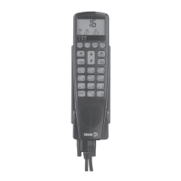
Procedure for connecting the handset directly to the VHF set.
Connecting external speakers to transceiver outputs via SPARC-bus.
Details of Handset Hook and SPARC-Bus Connection Box H4991 pin assignments.
Maximum cable lengths and wire specifications for SPARC-bus connections.
Pin assignments for connecting GPS and other optional equipment.
Maximum permissible lengths for power cables based on wire gauge.
Overview of electrical connection points on the transceiver unit.
Pinout configurations for connecting to Battery and N420 power units.
Cable specifications for connecting a printer to the VHF unit.
Recommended safety distances for magnetic compasses from the equipment.
Step-by-step guide for performing internal and external DSC call tests.
| Brand | Sailor |
|---|---|
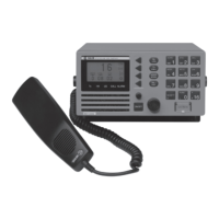
| Model | RT4722 |
| Category | Marine Radio |
| Language | English |