11
Installation
RT4722
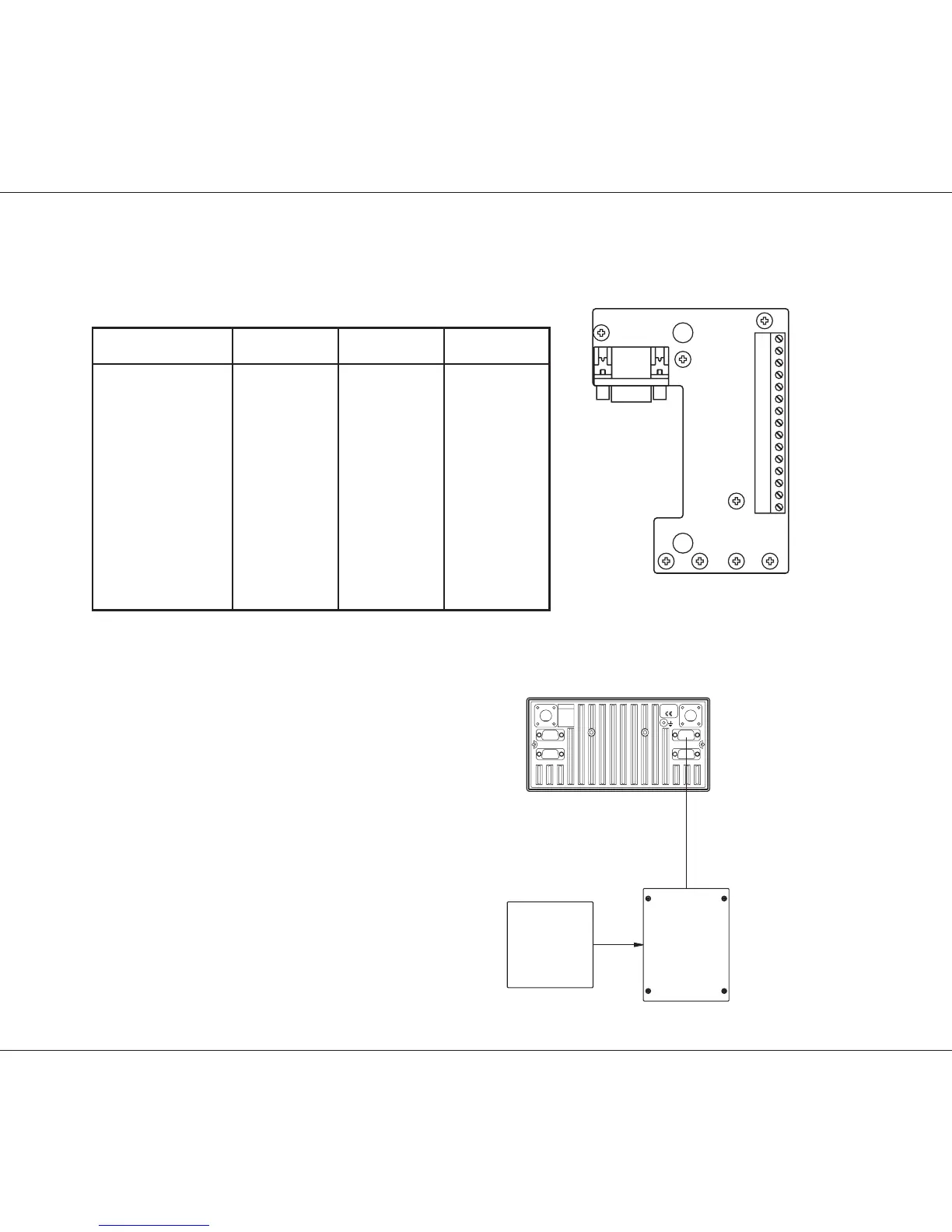
2.6.2 Options Connector H4992
Options connectors
Transceiver unit Twisted Option box
X2 Name pair X1,X2
pin 1 DSC_ALARM_ON 1
pin 2 NMEA_OUT+1 1 Optional
pin 3 NMEA_OUT-1 1 Optional
pin 4 NMEA_IN+ 2 4
pin 5 NMEA_IN- 2 5
pin 6 -BAT_0VDC 3 6
pin 7 +12VDC 3 7
pin 8 FAN_ON 8
pin 9 RX_1_SQ 9
pin 10 CH_AUX_1 10
pin 11 CH_AUX_1 11
pin 12 RX_1_AF 12
pin 13 N.C. 13
pin 14 N.C. 14
pin 15 N.C. 15
35350
NMEA_IN+
NMEA_IN-
-BAT
+12VDC
FAN_ON
RX_1_SQ
CH_AUX_1
CH_AUX_2
RX_1_AF
NMEA_OUT+
NMEA_OUT-
DSC_ALARM_ON
X1
14
15
13121110
X2
987654
1
32
To connect a GPS to the VHF transceiver, connect
the GPS signal lines to the options connector
pin_4 (NMEA_IN+) and
pin_5 (NMEA_IN-).
Alternatively the GPS can be connected directly
to the transceiver by means of a 15-pole high
density D-sub which is supplied with the radio,
in the same pins as those mentioned above.
(NMEA_IN+ and NMEA_IN-) To fasten the D-sub
on the transceiver, use the special 15 to 15-pole
adaptor, also supplied with the radio.
35407A
GPS H4992
56.111
SPARC-BUS
HANDSET PRINTER
OPTION
/
Tx
Rx
12V DC
9945