-3-
Plug cap
Switch (not included)
Capacity: more than 3A
Sensor
Sensor cord
Battery
Voltage: 6-8V
Capacity: 1,000mA or higher
Plug cord
Main unit
Battery cord
Noise check (required)
Fig.5
Fuel level
above
Fuel level
to Outside of
the fuselage
Air inhalation
pipe
Fig.4
Fig.3
Center of fuel tank
Within 200mm (close as possible)
Fire wall
Engine center
Fuel tank
(200-250cc in capacity)
Gasoline-proof tube
Filter with weight
Air inhalation
pipe
Fuel feeding pipe
to Carb nipple
Rubber cap for
gasoline-resistant
Fig.8
Fig.6
Fig.7
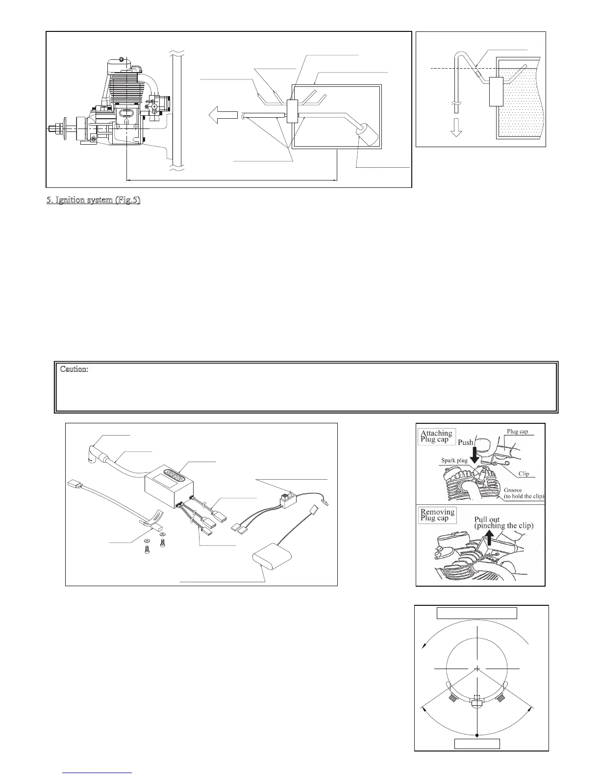
5. Ignition system (Fig.5)
The ignition system is designed to match our 4-stroke engines with automatic advancing system.
However this ignition system is designed to be an anti-noise product, please isolate it completely from the receiver, servo, and battery to
avoid a radio-interference trouble. Moreover, it is desirable to utilize a noise filter (line filter). Especially, each switch (for Ignition and
for Receiver) should be isolated and set far from each ones.
The function of each cord;
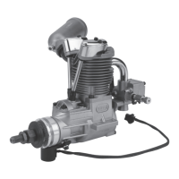
(1) Plug cord (meshed high tension cord)
The tip of the plug cap is designed exclusively for SAITO SP-1 Plug. When you put on the plug cap, insert it to the plug until the
clip fits the groove on the plug (Fig.6; then you will hear clicky sound) to avoid coming off during flight. And then pull the plug cap
to make sure that it won’t come off.
When you put off, pinch the clip and pull up the plug cap (Fig.7).
(2) Sensor cord (black /red/white cord)
Connect with the cord from the sensor attached to the engine.
(3) Battery cord (black/red cord)
Please use the fully charged battery that has adequate spec. (6-8V, more than 1000mA is recommended.). Between the battery and
main body, make sure to set an ignition switch whose capacity is higher than 3A.
Caution: A gasoline engine generates a noise which has an adverse effect on RC adjustment unlike a glow engine. Please be sure to carry out a
noise check each time while the engine is running before the flight. Since a noise which occurs during flight may lead to a large-scale accident,
please carry out a noise check without fail.
As a simple method, after starting engine you can check by removing the antenna of the transmitter and operate it about 50m away from the
airplane. If there is no malfunction, it is normal. Moreover, it is preferable to obtain advices from an expert of gasoline units.
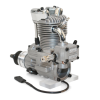
*Sensor position and Power / Starting easiness;
The ignition sensor can be moved to CW (advance the spark timing) or CCW (delay the timing) as Fig.8
shows.
At the factory default the sensor is fixed on the center (neutral) position. The reason is related to the
methods of engine starting.
・With an electric starter-You can start wherever the sensor is fixed.
So you can set the sensor as the rpm reaches maximum speed.
・By hand flip (Manual start)-Starting easiness depends on the sensor position.
The factory default is set as you can start by hand flip and also get highest rpm in that range as possible.
If you prefer easiness of hand starting, move the sensor to CCW direction to delay the spark timing. But
then the maximum rpm will slightly decline.
If you prefer power (highest rpm), move the sensor to CW direction. But then you can't start by hand
flip but only with starter.
In addition by the feature of the ignition system, it heats up with engine running. When you restart the
engine by hand flip, you should open the throttle valve slightly while it's hot. And it's better to enlarge
the choke without wetting the plug.
For safety we recommend to use an electric starter.
Neutral Position
Hand start
easy
area
Delay
Spark timing
Advance
Spark timing
CCW
CW
Prop rotation
(CCW)
View from front