17
ENGLISH
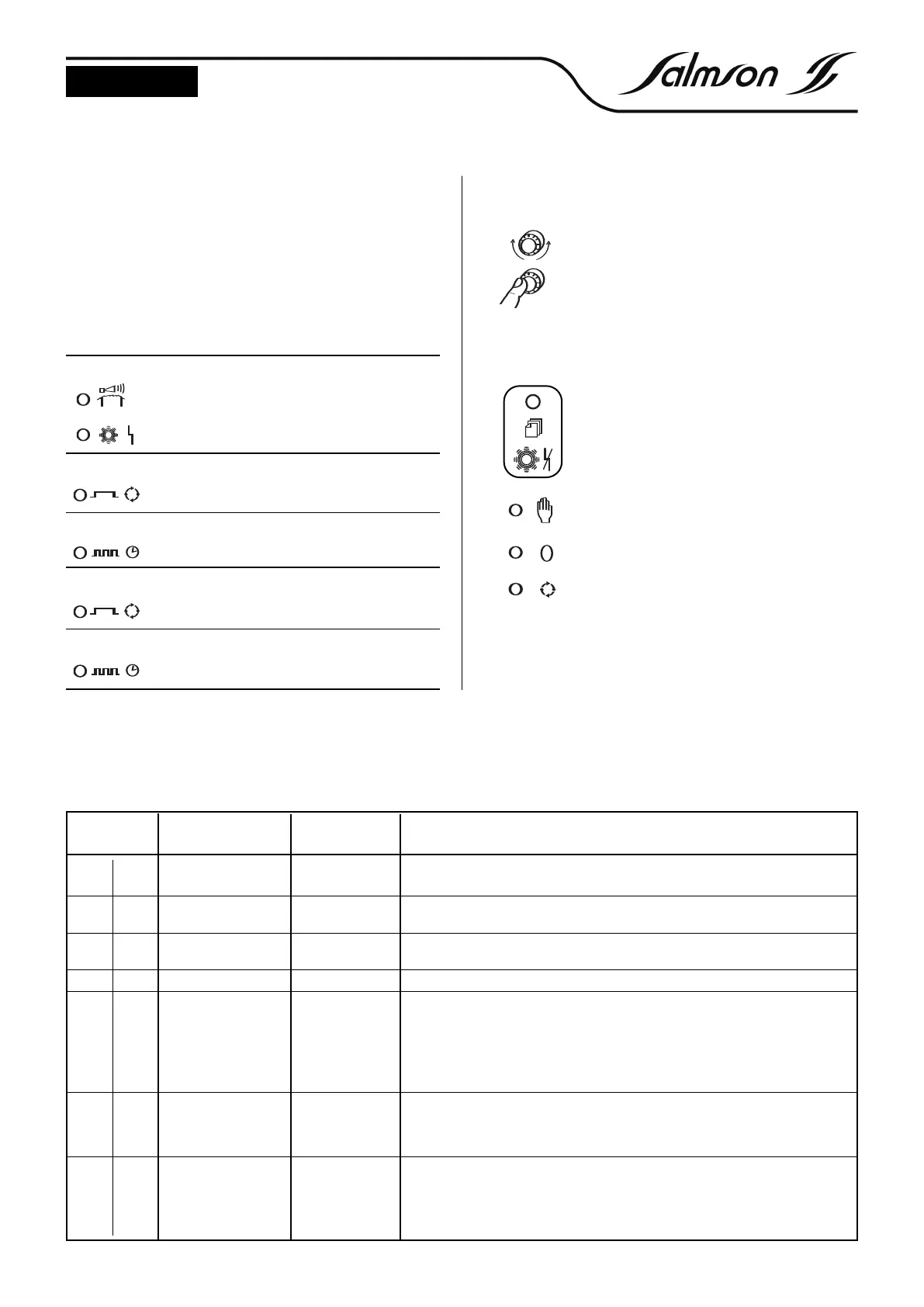
4.2.2 Control elements (See FIG. 3 - 4 - pos. 2)
Operating the knob
To select a new level or a new parameter, turn the
knob left or right.
To change to the new level or the confirm and
activate the new setting, briefly press the knob.
To change a setting, turn the knob until the desired setting is dis-
played. Then briefly press the knob. The last saved value blinks and
can now be changed. Turning the knob rapidly effects larger value
changes, turning it slowly allows fine adjustments to be carried out.
The rotary knob can be used to show all parame-
ter settings, operating hours, pump starts and the
motor current.
The rotary knob is used to stop the acoustic alarm
and to reset all faults after removing the underlying
cause. If the fault persists, only the the SSM relay and
the buzzer are desactivated.
The “Manual” button is used to switch on the
pump. The gr
een DEL blinks. After 2 min. the pump
is automatically switched off.
The “Zero” button is used to switch off the pump.
The green DEL extinguishes.
The “Auto” button is used to switch the pump via
the level. The green DEL lights stead.
4.2 Operation of the switching device
All signal and control elements are located on the front panel of the
switching device (
See FIG. 3 - 4).
The switching device is set and operated via buttons and a red but-
ton .
Changes to the settings (via the digital potentiometer) are immedia-
tely indicated in plain text in the LC display.
The liquid level is indicated in cm (with IPAE) (0-1 mCW).
The control electronics are housed in a wall mount housing (IP65).
4.2.1 Indicators (See FIG. 1 - 2 - pos. 1)
Red DEL lit
max. water level alarm
(or)
pump fault
Yellow DEL lit
pump operating
Yellow DEL blinks
pump operating via run-down time
Green DEL lit
automatic mode
Green DEL blinks
manual operation
4.2.3 Settings
The following table shows the possible settings. The line at the top of the display shows the option, the line at the bottom displays the value that
can be changed. The possible settings are listed in the order that is obtained when the digital potentiometer is turned clockwise.
Line in display
Possible setting
(in bold : pre-setting)
Base load ON 0-100 cm
Explanation
The v
alue determines the switch-on point of the first pump
Base load OFF 0-100 cm The v
alue deter
mines the switch-of
f point of the f
ir
st pump
Peak load ON 0-100 cm The value determines the switch-on point of the second pump
Peak load OFF 0-100 cm The value determines the switch-off point of the second pump
Maximum water level 0-100 cm When the set value is exceeded, the maximum water level alarm indication is dis-
play
ed, the maximum water level alarm DEL lights and the collective fault signal relay
and the maximum water level alarm relay are operated. The fault is automatically
ac
kno
wledged w
hen the le
v
el has f
allen by the set hysteresis, i.e. 5cmWS.
A
TTENTION!
Maxim
um w
ater level alarm < switch-on point = fault indication in the dis-
play
Runtime changeo
v
er
Deactiv
a
ted
1 - 60 min.
When the set time in base load mode is exceeded, a pump changeo
v
er is ef
f
ected.
The time only runs if neither the switch-off point was reached during the preselected
time nor the peak load pump was actuated. At the third changeover a collective
f
ault indication is output as w
ell
delay r
e-star
t
0 - 180 sec. Ensur
es that after a po
wer failure not all pumps (when several systems are in use) are
star
ted sim
ultaneously but in succession. When the pump has been selected, the
control has been set to automatic mode and power has been restored, the following
is displayed: ”Delay xx s”. The pump is not started until the set time has elapsed.
YN3100
I
YN3200
• •
• •
•
•
• •
• •
•
 Loading...