21
ENGLISH
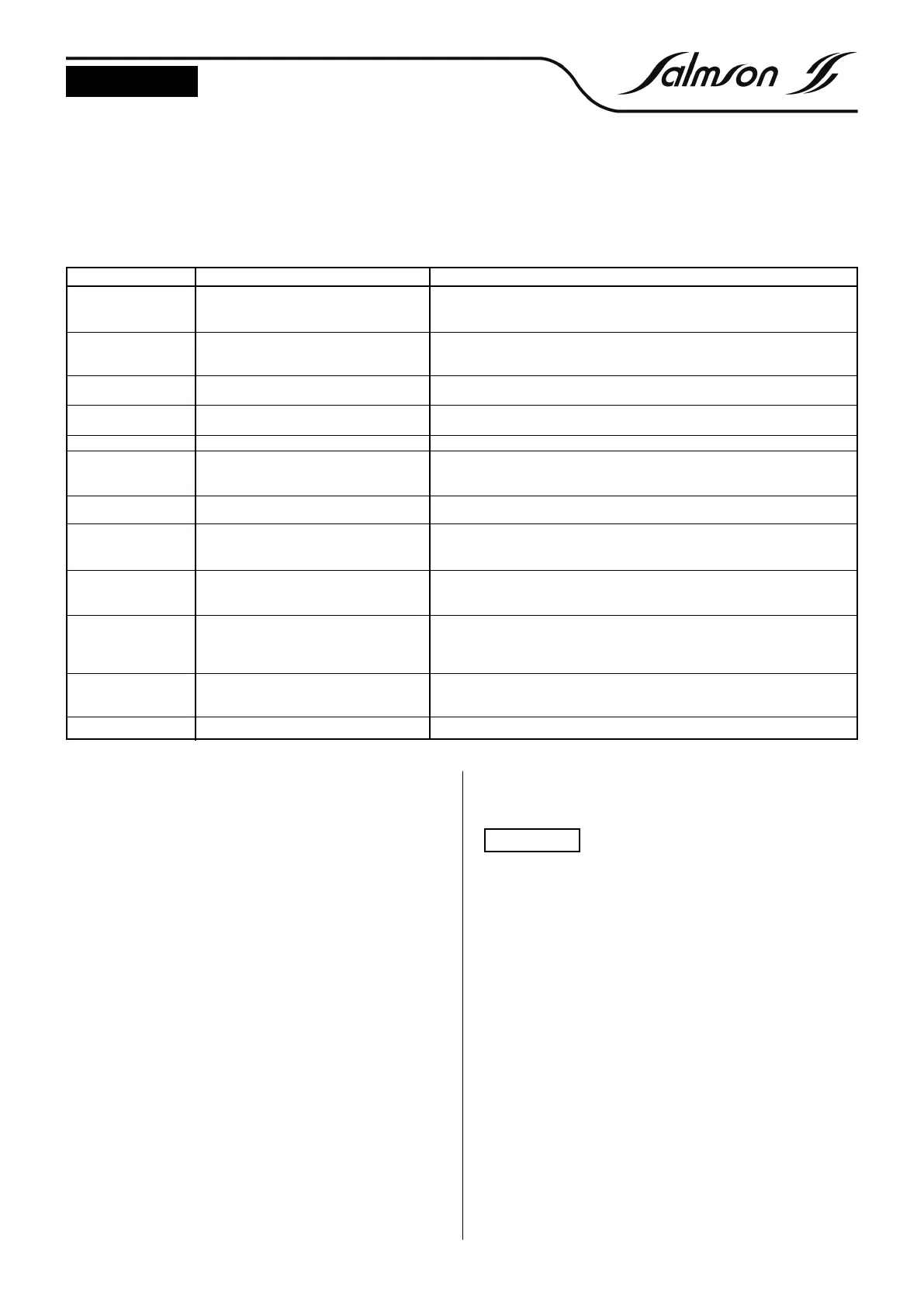
8. PROBLEMS, CAUSES AND REMEDIES
In case of system faults perform the following checks :
- Check for presence of foreign matter in the reservoir (in the bell).
- Check electrical connection (faulty fuse).
9. RETROFITS AND ACCESSORIES
9.1 Accessor
ies
Accessor
ies m
ust be or
dered separately.
- Electronic level sensor 0-1 mWS (4-20mA) with 10, 30 or 50m
connection cable.
- Safety barrier (zener barrier) in housing with connection cable
- Float switch.
-
Isolating switch amplif
ier for float switch for use in potentially explo-
sive areas.
-
Switch cabinet for outdoor installation (other accessories, e.g. swit-
ch cabinet heater, FI protection switch etc. available.
9.2 Assembly
- Mount switchgear.
- Perform settings.
- Functional check and start-up.
9.3 Electronic level IPAE sensor with zener barrier
For use in potentially explosive areas, a safety barrier (zener barrier)
m
ust be inserted between the sensor and the switch box.
9.3.1 Assembly
Electrical connection to terminals 25 and 26 :
The connection is m
ade as f
ollo
ws :
- Isolate control box from the power supply.
- Remove terminal cover from control box.
- Open housing with zener barrier.
-
Connect electronic sensor to zener barrier.
- Connect the connecting cables of the zener barrier to terminals 25
and 26 in the control box.
- Connect zener barrier to the potential equalisation (PA) (min. 4.0
mm
2
cooper).
Strictly follow the safety precautions for the zener
barr
ier
.
-
Close housing co
vers.
- Functional check and start-up.
Subject to technical alterations !
Indication in display
P1: Therm. fault 1
P2: Therm. fault 1
P1: Therm. fault 2
P2: Therm. fault 2
P1 : or P2 :
Overcurrent
P1 : or P2 : no load
Max. water level alarm
Max. water level float
Runtime alarm
Switch-on point
below switch-off point
Max. water level
below switch-on point
Switch-on point
above peak load
Faulty operation of
float switch
Interface < 3 mA
Fault description
Winding protection contact (WSK) of pump 1
or 2 has tripped (contact between terminals
31/32 or 38/39 has opened)
Winding protection contact (WSK) of pump 1
or 2 has tripped (contact between terminals
32/33 or 39/40 has opened)
The set motor limiting value has been excee-
ded
Phase L2 is not present or the control is opera-
ted without load
Level has exceeded the max. water level setting
Contacts of the float switch for max. water
level are closed, both pumps are activated or
are already active.
Triggered after third runtime changeover
The settings for switch-on and switch-off point
overlap
The setting for the max. water level alarm lies
below the switch-on point
The switch-on point of the base load pump
lies above the switch-on point of the peak
load pump
Plausibility check, float switches not connec-
ted in correct order
Current signal less than 3 mA
Remedy
Check pump; if clogged, remove foreign matter, if present. Check motor for sufficient
cooling (dry run)
Check pump; if clogged, remove foreign matter, if present. Check motor for sufficient
cooling (dry run)
Check motor current and set rated current; correct, if necessary
Check power supply; check pump and pump cable
Check pump for function or level setting
Check pumps for function or check float switch
Check pumps for function
Check level settings
Check level settings
Check level settings
Check float switches, check electrical connections
Check level sensor, check electrical connections
If the malfunction cannot be removed, please consult your sanitary and heating specialist or SALMSON Customer Service
If faults have occurred, they are shown alternately in the bottom line
on the display.
ATTENTION !
 Loading...